phase linear 400

gene french

Veteran and General Yakker
Joined
Mar 6, 2022
Messages
5,564
Location
guayabo de bagaces, guanacaste, costa rica....
Tagline
music...the healer of souls...
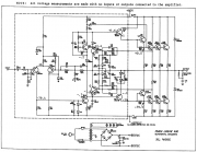
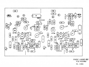
all transistors on the shown board checked good....those that were not definitive in circuit were removed from circuit and checked stand alone...
i dont show a q 10 on the driver board....my q10 is a xpl 909...
i now understand what gepetto was saying about mr. carver being a bit disorganized...
q9 and q13 did check good out of circuit...the bias transistors...as well as the diodes on the back plane...all were removed from circuit to check...
i presume you want me to install all 4 drivers (checked good out of circuit)...
and install 4 known good 909s in a row....i dont have enough to populate the whole backplane...or even two rows...
can i must move the 4 good ones up a row to as i only have 7 known good chips...or will just one row prove my driver board is safe and operational...
i do have a matched set on the way...evidently out of a 700...because there are 10...
thank you for your help...
 

Attachments

WOPL Sniffer

Veteran and General Yakker
Joined
Aug 10, 2015
Messages
11,522
Location
Minnie-Soda
Tagline
Screw it
Care must be taken with those old parts when removing them from the circuits for testing. The extra heat from removal and replacement will take some life out of what is left. Heat is the enemy.
 

Gepetto

Administrator
Staff member
Joined
May 15, 2011
Messages
14,045
Location
Sterling, MA
Tagline
Old 'Arn Enthusiast
all transistors on the shown board checked good....those that were not definitive in circuit were removed from circuit and checked stand alone...
i dont show a q 10 on the driver board....my q10 is a xpl 909...
i now understand what gepetto was saying about mr. carver being a bit disorganized...
q9 and q13 did check good out of circuit...the bias transistors...as well as the diodes on the back plane...all were removed from circuit to check...
i presume you want me to install all 4 drivers (checked good out of circuit)...
and install 4 known good 909s in a row....i dont have enough to populate the whole backplane...or even two rows...
can i must move the 4 good ones up a row to as i only have 7 known good chips...or will just one row prove my driver board is safe and operational...
i do have a matched set on the way...evidently out of a 700...because there are 10...
thank you for your help...
Hello Gene
Can I assume that when you are checking your transistors you are checking each junction in both directions AND you are checking the C-E path as OPEN in both directions.

Sometimes transistors will fail with a short between C-E but the B-C and B-E junctions seem to measure normally.
 

gene french

Veteran and General Yakker
Joined
Mar 6, 2022
Messages
5,564
Location
guayabo de bagaces, guanacaste, costa rica....
Tagline
music...the healer of souls...
Hello Gene
Can I assume that when you are checking your transistors you are checking each junction in both directions AND you are checking the C-E path as OPEN in both directions.

Sometimes transistors will fail with a short between C-E but the B-C and B-E junctions seem to measure normally.
yes sir...and i am using an analog meter.....i saw no collector to emitter shorts...but, i will check again....just to be sure...
i did miss the reversed cap....to quote mr. obama...never underestimate my ability to mess things up....
 

laatsch55

Administrator,
Staff member
Joined
Jan 14, 2011
Messages
74,922
Location
Gillette, Wyo.
Tagline
Halfbiass...Electron Herder and Backass Woof
Ok, bottom row will be the 410's, next row will be the 909's. You can test the amp in that configuration.
Please answer the following questions.
Do you know how to check bias?
Do you know how to adjust bias?
 

gene french

Veteran and General Yakker
Joined
Mar 6, 2022
Messages
5,564
Location
guayabo de bagaces, guanacaste, costa rica....
Tagline
music...the healer of souls...
Ok, bottom row will be the 410's, next row will be the 909's. You can test the amp in that configuration.
Please answer the following questions.
Do you know how to check bias?
Do you know how to adjust bias?
yes, sir...i do...mr joe sent me a diagram ....the pots on my board are r14 left and right...i adjusted before and set it for .35v....as per mr. joes instrucitons...should the bias have changed?? the q6 a9 q13 are still the same.....shouldnt it be pretty close??
i can check the bias without all of the outputs??
i had the offset less than 1mv from 0 and the bias set at less than .1 mv
both were almost exact...according to the manual...
 

laatsch55

Administrator,
Staff member
Joined
Jan 14, 2011
Messages
74,922
Location
Gillette, Wyo.
Tagline
Halfbiass...Electron Herder and Backass Woof
Yes, bias will be close even with a limited amount of outputs. What we want to know as you bring up the amp is if the bias is behaving. Blown outputs can affect the bias circuit. Monitor bias as you bring up the amp. Also, in the WOPL archives is a transistor testing thread that may help..
 

gene french

Veteran and General Yakker
Joined
Mar 6, 2022
Messages
5,564
Location
guayabo de bagaces, guanacaste, costa rica....
Tagline
music...the healer of souls...
i have the drivers installed....i rechecked the 4 transistors ...
if i install 4 909s in the row above the drivers...and it works...does that mean the other rows above are good and the board has been deemed working??? or will i need to keep going up to check....remember i only have 7 good 909s...i can only populate one row at a time...
 

laatsch55

Administrator,
Staff member
Joined
Jan 14, 2011
Messages
74,922
Location
Gillette, Wyo.
Tagline
Halfbiass...Electron Herder and Backass Woof
What that means is everything is fine the way you are. When you get the new outputs you can install a row at a time and bring it up on the DBT each time. It's certainly good news it's ok to this point..
 

gene french

Veteran and General Yakker
Joined
Mar 6, 2022
Messages
5,564
Location
guayabo de bagaces, guanacaste, costa rica....
Tagline
music...the healer of souls...
ok....here is where i am...
no speakers no inputs connected....
i brought it up on dimbulb tester...normal result....bright bulb dimming followed...
i heard the protect relay click....and upon power down it clicked again after a few seconds....these new caps holds the voltage a while...
but, again, normal result...as i remember the behavior of the relay while it was working...
i did not touch the bias....no warmup....started at .200v quickly climbed to .300v when it hit .325v was ticking very slowly up....it is not far off...both sides acted the same and produced similar results...as when i set it the first time...again no warmup...
the offset on one side was a little over 50mv...and around 60mv on the right channel....still under the 75mv limit...i think no danger....
i did not adjust....i dont think it will without the rest of the finals...
i did not leave it running long...just long enough to verify the protect relay was again operating...it clicks less than 1 second after power on...
and long enough to see the bias was not running away....
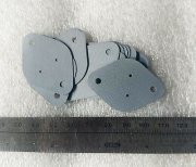
those clear insulating pads are very brittle and delaminating....i really need to change them...i will see if amazon has them and put them on my next order....what are they called?? besides little clear insulating pads that go under my transistors????
thanks...i think good news today....and maybe it was just the reversed cap that threw me over the cliff....and i did not burn down the barn...
 

George S.

Veteran and General Yakker
Joined
Feb 18, 2020
Messages
5,036
Gene, we no longer use the mica insulators and compound under the outputs. Now we use T03 silicone rubber thermal pads with no compound. They are superior in transferring heat. Bergquist makes the best ones.
1649103890012.png
 
Top