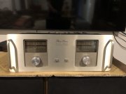
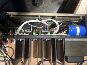
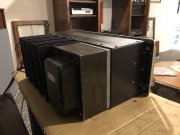
WOPL Phase Linear 700 ll for sale / trade

grapplesaw

Veteran and General Yakker
Joined
Aug 13, 2014
Messages
2,775
Location
Vancouver
Tagline
---
#1
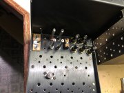
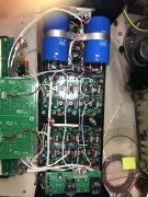
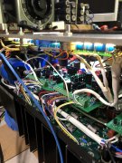
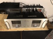
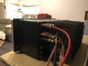
I have used this for daily use. It is surplus due to addition of WOPL D500

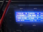
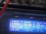
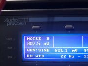
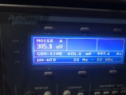
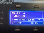
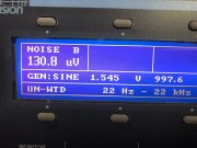
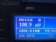
The good-this amp has excellent low noise as low distortion . Please see photos.

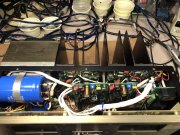
The bad- top cover could use repainting but I didn’t want to lose the PL lettering.

Contact me if you want to buy ( no low ball offers please as we all know what is worth)

E80E5541-ECD8-4BF9-8EB0-B46268A42C8E.jpeg BFCEFB7F-5EB0-4F75-BDD2-857986A7955B.jpeg D34BF456-51DF-4A40-8801-DA077B1DB8D4.jpeg 3BD00423-AB43-46EA-B699-A13E9E3E2FAD.jpeg D445B85F-6F89-4C20-9F52-A40145FE85D6.jpeg 9E82C787-169A-4951-B0A3-1AA521CF83D4.jpeg 8B0C9089-9AC7-4C25-ADB9-61BBB1ABF0A0.jpeg C3564956-A940-4D78-950F-27B0FD3AD379.jpeg 7A3B59A5-FC56-4D22-B2C4-8D8E85CE17BD.jpeg A21F098D-8DD9-4ABF-91E2-E693FFF5D23F.jpeg
 
Last edited:

grapplesaw

Veteran and General Yakker
Joined
Aug 13, 2014
Messages
2,775
Location
Vancouver
Tagline
---
#2
Now that everyone is excited about units for sale on other sites at higher costs. don’t miss out on a fantastic amp as I am going to list in the market
 

Gepetto

Administrator
Staff member
Joined
May 15, 2011
Messages
13,915
Location
Sterling, MA
Tagline
Old 'Arn Enthusiast
#3
Now that everyone is excited about units for sale on other sites at higher costs. don’t miss out on a fantastic amp as I am going to list in the market
Hi Glen
You may be able to knock the noise A and B even lower if you cut in the wire change that I recently posted here. It is very low now and may be able to go lower.
 

Gepetto

Administrator
Staff member
Joined
May 15, 2011
Messages
13,915
Location
Sterling, MA
Tagline
Old 'Arn Enthusiast
#5
Thanks Joe
I’ll look for that post and try it out
First:

It is ESSENTIAL that you have the copper plate installed and connecting the 2 RCA input jacks. This shunts any external ground loops associated with cable connections from entering the amp’s separate signal paths and creating various degrees of ground looping. In other words, it makes the amp INTERNALLY immune to cabling effects from outside the amp. This does not say that you cannot still have external ground looping, it does say that this keeps the amp internals out of the equation. No build I have ever done has removed this copper plate. Remember, the RCA jacks and this copper plate MUST be isolated from the chassis.


Second:

Disconnect and remove the two ground wires running from the backplane pin 5L and 5R which run to the control board pin 5L and 5R Phoenix connector.

Along the bottom, run two new, separate 22AWG wires from a single solder lug on the single point ground copper bus bar to pin 5L and 5R on the control board. The solder lug goes underneath the 10-32 (or M5 if you have our newer caps) screw on the bottom B- bulk cap positive terminal which attaches to the copper bus bar. The wire to 5L is approximately 5” long and the wire to 5R is approximately 10” long, your measurements may be adjusted to suit how you lace these in. You should be able to use one of the #10 solder lugs provided in the White Oak Audio wire kits to accomplish this.


Dress and button up the amp reinstalling all covers.
 

grapplesaw

Veteran and General Yakker
Joined
Aug 13, 2014
Messages
2,775
Location
Vancouver
Tagline
---
#6
First:

It is ESSENTIAL that you have the copper plate installed and connecting the 2 RCA input jacks. This shunts any external ground loops associated with cable connections from entering the amp’s separate signal paths and creating various degrees of ground looping. In other words, it makes the amp INTERNALLY immune to cabling effects from outside the amp. This does not say that you cannot still have external ground looping, it does say that this keeps the amp internals out of the equation. No build I have ever done has removed this copper plate. Remember, the RCA jacks and this copper plate MUST be isolated from the chassis.


Second:

Disconnect and remove the two ground wires running from the backplane pin 5L and 5R which run to the control board pin 5L and 5R Phoenix connector.

Along the bottom, run two new, separate 22AWG wires from a single solder lug on the single point ground copper bus bar to pin 5L and 5R on the control board. The solder lug goes underneath the 10-32 (or M5 if you have our newer caps) screw on the bottom B- bulk cap positive terminal which attaches to the copper bus bar. The wire to 5L is approximately 5” long and the wire to 5R is approximately 10” long, your measurements may be adjusted to suit how you lace these in. You should be able to use one of the #10 solder lugs provided in the White Oak Audio wire kits to accomplish this.


Dress and button up the amp reinstalling all covers.
Got it
 

Mohawk

Chief Journeyman
Joined
Oct 29, 2019
Messages
709
Location
Ontario Canada
#9
Hi Glen
You may be able to knock the noise A and B even lower if you cut in the wire change that I recently posted here. It is very low now and may be able to go lower.

Hey Joe,

I'm pretty sure you have covered this before but what is the reason for the copper plate specifically ?

Electrically I can't get my head around what the difference would be if you "tie" the rca's together with a wire isolated just as the copper plate ...

M
 

Gepetto

Administrator
Staff member
Joined
May 15, 2011
Messages
13,915
Location
Sterling, MA
Tagline
Old 'Arn Enthusiast
#10
Hey Joe,

I'm pretty sure you have covered this before but what is the reason for the copper plate specifically ?

Electrically I can't get my head around what the difference would be if you "tie" the rca's together with a wire isolated just as the copper plate ...

M
Electrically, a wire works just as well. The copper plate is easier because it is there in the original build.
 

ABebar

Journeyman
Joined
May 28, 2021
Messages
177
Location
Warrenville, IL
#12
First:

It is ESSENTIAL that you have the copper plate installed and connecting the 2 RCA input jacks. This shunts any external ground loops associated with cable connections from entering the amp’s separate signal paths and creating various degrees of ground looping. In other words, it makes the amp INTERNALLY immune to cabling effects from outside the amp. This does not say that you cannot still have external ground looping, it does say that this keeps the amp internals out of the equation. No build I have ever done has removed this copper plate. Remember, the RCA jacks and this copper plate MUST be isolated from the chassis.


Second:

Disconnect and remove the two ground wires running from the backplane pin 5L and 5R which run to the control board pin 5L and 5R Phoenix connector.

Along the bottom, run two new, separate 22AWG wires from a single solder lug on the single point ground copper bus bar to pin 5L and 5R on the control board. The solder lug goes underneath the 10-32 (or M5 if you have our newer caps) screw on the bottom B- bulk cap positive terminal which attaches to the copper bus bar. The wire to 5L is approximately 5” long and the wire to 5R is approximately 10” long, your measurements may be adjusted to suit how you lace these in. You should be able to use one of the #10 solder lugs provided in the White Oak Audio wire kits to accomplish this.


Dress and button up the amp reinstalling all covers.
I'm assuming that this would apply to a WO PL400 as well?
 
Joined
May 26, 2013
Messages
713
Location
St. Louis, MO.
Tagline
Born and Raised In The 700 Watt Club.
#16

grapplesaw

Veteran and General Yakker
Joined
Aug 13, 2014
Messages
2,775
Location
Vancouver
Tagline
---
#17
Hi Glenn. I don’t know if you got the chance to view this specific thread recently, but it’s the one Joe’s referring to above.

https://forums.phxaudiotape.com/threads/my-fathers-continuing-saga.4575/page-15#post-302769

-Dave
Hi Dave
I did a quick read on it. I have a question for you. Did you do any measurement’s using a 1000 ohm resistor to short the inputs. This is what I use. Also did the 400’s have the same results as the 700. You may have it there so I will go over your thread again. I’ll compare the direct short and the 1000 ohm results.

I will be testing the new 700b build over the weekend and report how it does. I will try a couple of variations of the pin 5 grounds. While I’m at it I’ll compare a d500 and 400 ll to the B with similar ground changes. I am not convinced that tying the two grouds together makes any difference especially using the dual mono board. Stay tuned as I may be wrong.

Here are some observations I have regarding the 700b and the 700 series ll I’ve bult. These are that a few , not all, single wond transformer of the 700b actually puts out a couple more volts than the dual wound series ll for same line voltage. Moreover the B transformer does not fall off as much as the series ll does at full output and therefore makes about 20-30 more watts before clipping. Now making all the upgrades does not change a given amps output from stock but different winds can.

Some B’s actually vibrate at idle . Not as much as the d500 but more than the 700 ll. I am sure someone outthere can explain it better than me but in essence these are all the same frame and size transformer but the more you get out the more stationary vibration there is. This does not effect the noise floor but is audible to some degree.
 
Last edited:

grapplesaw

Veteran and General Yakker
Joined
Aug 13, 2014
Messages
2,775
Location
Vancouver
Tagline
---
#18
Well just starting in on powering up the new B

So after first sorting out I set to check the residual noise. Now full disclosure I went and added a shielded wire with shield bonded to the bus bar only. How could this not hurt. Will first test was typical 500uv left and .300 right Not bad right. Well after all the detail I put in on laying his puppy out there was no gain. But waited when I separated the two ground wires as far it could the readings went crashing down 130uv right and179 left. Well I got to finish this one off and I will leave the wires as they are. But this leaves a magnitude of questions and things to do with these two ground wires. And this is with 1000ohm jumper across the input image.jpg D2A91814-ED6D-43B5-92DC-B91D3A9F9701.jpeg D78ADC8F-9FF0-4B40-874E-B92EE0FEEEC1.jpeg

So no conclusion today.
 

Gepetto

Administrator
Staff member
Joined
May 15, 2011
Messages
13,915
Location
Sterling, MA
Tagline
Old 'Arn Enthusiast
#19
Well just starting in on powering up the new B

So after first sorting out I set to check the residual noise. Now full disclosure I went and added a shielded wire with shield bonded to the bus bar only. How could this not hurt. Will first test was typical 500uv left and .300 right Not bad right. Well after all the detail I put in on laying his puppy out there was no gain. But waited when I separated the two ground wires as far it could the readings went crashing down 130uv right and179 left. Well I got to finish this one off and I will leave the wires as they are. But this leaves a magnitude of questions and things to do with these two ground wires. And this is with 1000ohm jumper across the input View attachment 64168 View attachment 64169 View attachment 64170

So no conclusion today.
Short your inputs and you should go even lower Glen. 109dB SNR is not too shabby.
 
Top