Thanks Joe
I’ll look for that post and try it out
First:
It is
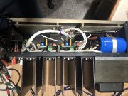
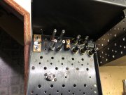
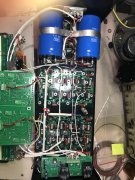
ESSENTIAL that you have the copper plate installed and connecting the 2 RCA input jacks. This shunts any external ground loops associated with cable connections from entering the amp’s separate signal paths and creating various degrees of ground looping. In other words, it makes the amp INTERNALLY immune to cabling effects from outside the amp. This does not say that you cannot still have external ground looping, it does say that this keeps the amp internals out of the equation. No build I have ever done has removed this copper plate. Remember, the RCA jacks and this copper plate
MUST be isolated from the chassis.
Second:
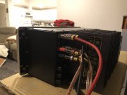
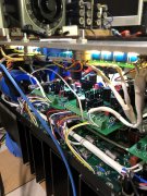
Disconnect and remove the two ground wires running from the backplane pin 5L and 5R which run to the control board pin 5L and 5R Phoenix connector.
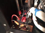
Along the bottom, run two new, separate 22AWG wires from a single solder lug on the single point ground copper bus bar to pin 5L and 5R on the control board. The solder lug goes underneath the 10-32 (or M5 if you have our newer caps) screw on the bottom B- bulk cap positive terminal which attaches to the copper bus bar. The wire to 5L is approximately 5” long and the wire to 5R is approximately 10” long, your measurements may be adjusted to suit how you lace these in. You should be able to use one of the #10 solder lugs provided in the White Oak Audio wire kits to accomplish this.
Dress and button up the amp reinstalling all covers.