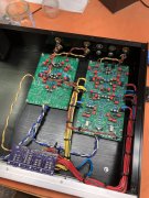
Comparing battery-powered phono pre-amps, from RS ($$) to ASR ($$$$) ... and beyond!
- Thread starter D-500 Flogger
- Start date
- Joined
- Nov 15, 2021
- Messages
- 482
- Location
- near Liverpool, NY
- Tagline
- Lifelong student / listening = bliss
My first post on this subject will discuss what can you do with a stone stock 25+ year-old Radio Shack battery-powered phono preamp?
1) Due to the small physical movement of the needle as it traces the tiny lateral wiggles in a record groove, a Moving Magnet phono cartridge only generates a 2.5 to 5 millivolt peak signal. In order to bring this phono signal up to the same level as a tuner, tape deck, or CD player, the phono stage has to amplify the cartridge signal an *additional* 34-40 dB. (!) Given this, the phono stage is much more susceptible to any stray magnetic field, AC ripple, hum, buzz, etc., inside the confines of our AC-powered preamp than a regular line level input.
IF moving this amplification to a external battery-powered phono preamp makes for better sound from your turntable, then you *know* that a) there's room for improvement, and b) you have a good idea of where the improvement needs to happen.
In the attached hand-drawn graph, I have a hypothetical example. I have a PL 2000 preamp that's ~45 years old, and I had originally retired it back in the early '90s after figuring out the excess background hiss and a low-level hum was due to aging components. Let's say that today it gets hooked up to the Dual TT, PL 400 S2 amp, and a set of Infinity Qe bookshelf speakers, and after careful measurements in the listening position, I determine that the total dynamic range from the loudest clean output (100 dB) to the quietest hiss/hum with the system idle (45 dB) is 55 decibels total.
I then plug the Dual TT into the RS phono preamp, and that in turn is plugged into the AUX input on the PL 2000 preamp. The tests are re-run, and now the peak level remains the same, (100 db) but now the hum is gone & the hiss is reduced to the point where the noise floor is 6 dB lower at the listening position. Voila! I now have a total dynamic range of 61 dB, a 6 dB improvement:
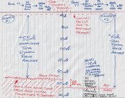
(Apologies for the caveman graphics...)
NOTE: There is no doubt that there's even more room for improvement available from the 25 year old RS phono preamp -- but only a +6 db improvement is discernable due to the fact that the noise floor of the 45-year-old AUX input stage is the new low-level LIMFAC. So let's say that I decide to go through my PL 2000 just like George S did, and I bring this preamp all the way up to 2022 performance levels?
Q1: Is it possible that the restored 2000 preamp now has a quieter phono stage than the 25-year-old RS phono preamp with dried-up electrolytic coupling capacitors & carbon film resistors? Let's say that this *is* the case! Now what?
Q2: If we go through and renew/upgrade the components in the RS phono preamp with today's technology, will this (combined with the dead-silent battery power) once again provide the lowest possible noise floor/maximum dynamic range when combined with the cleaned up PL 2000 preamp?
Will the cleaned up PL 2000 combined with the 2022 version of the RS phono preamp now be capable of a better total Dynamic Range? Possibly the circuit is now better than what the cartridge is able to extract from the record groove? (If so, perfect - stop here & start carefree listening mode! :0)
****
In the next post we will take a closer look at hot-rodding the RS phono preamp, with the goal of maximizing the signal/noise ratio to today's standards.
1) Due to the small physical movement of the needle as it traces the tiny lateral wiggles in a record groove, a Moving Magnet phono cartridge only generates a 2.5 to 5 millivolt peak signal. In order to bring this phono signal up to the same level as a tuner, tape deck, or CD player, the phono stage has to amplify the cartridge signal an *additional* 34-40 dB. (!) Given this, the phono stage is much more susceptible to any stray magnetic field, AC ripple, hum, buzz, etc., inside the confines of our AC-powered preamp than a regular line level input.
IF moving this amplification to a external battery-powered phono preamp makes for better sound from your turntable, then you *know* that a) there's room for improvement, and b) you have a good idea of where the improvement needs to happen.
In the attached hand-drawn graph, I have a hypothetical example. I have a PL 2000 preamp that's ~45 years old, and I had originally retired it back in the early '90s after figuring out the excess background hiss and a low-level hum was due to aging components. Let's say that today it gets hooked up to the Dual TT, PL 400 S2 amp, and a set of Infinity Qe bookshelf speakers, and after careful measurements in the listening position, I determine that the total dynamic range from the loudest clean output (100 dB) to the quietest hiss/hum with the system idle (45 dB) is 55 decibels total.
I then plug the Dual TT into the RS phono preamp, and that in turn is plugged into the AUX input on the PL 2000 preamp. The tests are re-run, and now the peak level remains the same, (100 db) but now the hum is gone & the hiss is reduced to the point where the noise floor is 6 dB lower at the listening position. Voila! I now have a total dynamic range of 61 dB, a 6 dB improvement:

(Apologies for the caveman graphics...)
NOTE: There is no doubt that there's even more room for improvement available from the 25 year old RS phono preamp -- but only a +6 db improvement is discernable due to the fact that the noise floor of the 45-year-old AUX input stage is the new low-level LIMFAC. So let's say that I decide to go through my PL 2000 just like George S did, and I bring this preamp all the way up to 2022 performance levels?
Q1: Is it possible that the restored 2000 preamp now has a quieter phono stage than the 25-year-old RS phono preamp with dried-up electrolytic coupling capacitors & carbon film resistors? Let's say that this *is* the case! Now what?
Q2: If we go through and renew/upgrade the components in the RS phono preamp with today's technology, will this (combined with the dead-silent battery power) once again provide the lowest possible noise floor/maximum dynamic range when combined with the cleaned up PL 2000 preamp?
Will the cleaned up PL 2000 combined with the 2022 version of the RS phono preamp now be capable of a better total Dynamic Range? Possibly the circuit is now better than what the cartridge is able to extract from the record groove? (If so, perfect - stop here & start carefree listening mode! :0)
****
In the next post we will take a closer look at hot-rodding the RS phono preamp, with the goal of maximizing the signal/noise ratio to today's standards.
Last edited:
- Joined
- Nov 15, 2021
- Messages
- 482
- Location
- near Liverpool, NY
- Tagline
- Lifelong student / listening = bliss
1) How to get the most out of these phono preamps in stock condition.
The hot setup for running these RS preamps was the trick to not run (1) of these with both L & R signals through it simultaneously. Instead, they would purchase (2) of these, and run the L channel phono signal through 1, and the R channel phono signal through the other. Supposedly this would make the resulting sound much better. Obviously the L <> R separation (crosstalk) would improve, but since the only other variable is halving the load on the battery/C11 combo (see schematic) ...these reports are a good hint that we can (& should) make improvements in this area.
NOTE: The twin phono preamp dudes would recommend running 100K ohm shorting caps on the unused input of each phono stage. Makes sense.
****
So there you go. There's running stone stock -- and running stone stock x 2 for the Dual Mono bragging rights... :0)
I’d take that theory to the next level-
Run balanced from the cartridge: hot to left; cold to right, on each preamp. You’ll increase gain without increasing distortion. Plus benefit from balanced line noise rejection. Very handy with milivolt signals.
I’m making my Rega output this way, using Mogami Neglex Quad mic cable. I’m terminating the cable with an RCA (because I have a single ended phono pre) but all I’d need to do is change the RCAs to XLRs and plug ‘er in.
I’m using mini XLRs at the table to reduce bulk. These are used on headphones these days so more popular than the 3-pin Lemo connectors I was planning to use (also less expensive).
I have been thinking about new cables system-wide, and I will probably make up the new ones with this recipe. (Amphenol Audio has some nice RCA connectors for reasonable money)
Edit- this might give you enough gain to run MC…
- Joined
- Nov 15, 2021
- Messages
- 482
- Location
- near Liverpool, NY
- Tagline
- Lifelong student / listening = bliss
2) How to mod these phono preamps -- which parts in which order, & why
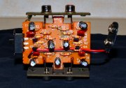
Also, here's a marked up copy of the schematic so that you can see the signal paths through the preamp:
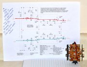
In order to take an 25+ year-old module and bring it back to new/better than new performance, the basic concept is to remove obsolete/end-of-life (dried out) components and repopulate the module with newer/better parts. (ie: A basic renewal instead of a redesign.)
Here's something I drew up to break this module upgrade into 3 steps:
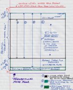
Arrow (1) shows what the claimed 50 dB signal/noise ratio of a new board with the stock components to give you a visual perspective.
Arrow (2) is showing the theoretical dynamic range improvement available if a perfectly stable 9V power is fed to our (4) transistors on the board. Of course the way I drew it could make one think that I'm saying that there would be more gain from the circuit at all times, even with a steady-state test tone. I am not saying that. Instead, I am trying to fix the 9v power 'bouncing' underneath our active devices during transient demands.
Instead, to help illustrate this point, let's on purpose temporarily worsen the design & see what happens. Let's remove the original 100uf C11 (upper lefthand corner of schematic, physically located right between the L & R output jacks on the board) ...and install a *1* ufd cap in it's place.
You see, the battery isn't plugged directly into the module; instead, the obvious need for battery servicing by the human & product packaging reasons the battery is electrically connected to the board by a ~4" pair of red/black wires. So, when a Bonham crescendo comes along, the transistors draw current simultaneously, the replacement current can't be sourced from the battery fast enough, so C11, acting like the on-board 9V 'water tower', keeps the pressure (voltage) steady in our power circuit. (this function is referred to as "Transient Load Decoupling", section 4 of this wiki entry.)
But remember, at the C11 position we took out the original 100 ufd cap & replaced it with a 1 ufd cap. So now, instead of our 4 active components having a (relatively) unwavering power source to draw from, the instantaneous voltage is dependent upon the relationship between the battery & wiring vs. the rate of instantaneous current draw by the 4 transistors.
With a 1 ufd cap in place, now our listening experience to complex, dynamic music will *vary* depending upon the internal design of different vendor's batteries - the more expensive ones that can deliver the current more rapidly will 'sound better' (soundstage won't collapse during transients, impact/slam won't disappear, etc) ...as opposed to the cheaper batteries where the internal design is 'good enough/cheap enough' to work in non-critical (normal) usage. I would posit that with the worst-case battery setup, that during a Bonzo bass drum triplet that the 1st kick would sound different than the 3rd kick. (Approx. 1:20 into this very interesting video.)
Given the above, when some of the more critical listeners would say a) this battery powered phono preamp sounds better with brand X battery vs. brand Y, I believe that they were on to something. (But they were derided in public by some for saying this.) Furthermore, the ones that said that instead of using 1 preamp in stereo mode, that using 2 at a time, 1 for each channel, the sound was further improved...I also believe that.
(NOTE: At this instant in time I wish I had the lab put together, for I would put the 1 ufd C11-equipped phono preamp against the (stock) 100 ufd. And I would set it up so that the viewer could actually hear the differences in the music while also watching the bouncing vs. nonbouncing 9v traces on the scopes. So now that they know what to look for, we would experiment with listening to the (stock) 100 ufd vs. a 470 ufd or even a 1000 ufd. Q: Where does the sonic benefit start to taper off? A: I don't know...yet. (!)
****
To put this into perspective, let's go back and revisit those 'cost no object' battery-powered phono preamps. For example, where the cost-conscious Korean bean-counters allowed our designer to use a 100 ufd capacitor at C11 -- meanwhile, the ASR Basis Exclusive uses a whopping 400,000 ufd of local storage for this same exact 'Transient Load Decoupling" function. (!) There's a lot that I don't know, but I *do* know that if we were to put 400,000 ufd of local storage & connected it to the C11 position, we would no longer be able to hear the differences between battery brands, no matter how dynamic the music we are listening to. (Actually, once it was charged up, we could completely remove the 9v battery...and the music would simply play on! :0)
****
OK, so after reading all this, I haven't even given the reader an upgrade recommendation for this critical C11 position. But if you read through this post, here is something that you can do. Remember the eBay guy selling this same preamp that has been 'recapped for better performance' for $99? If you go back to entry #46 & look at his photo, you will see that he did *not* upgrade C11 from the stock size?
Was he right, or was he wrong? At the moment, I had to admit that all of the above is pure conjecture...but once I put my audio test lab together & make some real-world measurements I will be able to come back to this discussion & tell you if 100ufd is really all you need...or that I found a 470 ufd from Panasonic that is thin enough to swap in + short enough to fit back into the stock box. (~75 cents apiece) ...but the real deal, sonically speaking is to mount this board inside a cigar box , giving you plenty of room to fab up a Panasonic (10) x 1000 uf array =10,000 uf cap bank for a scant $6.75 to the door:

(And yes, I know that the caps with a good reputation are being counterfeited. And that you can probably improve on the price at a digikey or mouser -- but I just needed a quick screen grab showing how it would be possible to improve local storage a 100 times (100 ufd > 10,000 ufd) in this position for <10 bucks + cigar box + cap bank wiring.)
Just food for thought. No doubt 10K uf is overkill for this preamp, and of course 1uf is too little -- so in order to come up with an intelligent, defensible answer we need to instrument *and* listen at the same time in order to come up with some hard-won power subsystem knowledge...of course, the 'non-bean counter restricted answer' is somewhere between these extremes...
In the interest of science!
Last edited:
- Joined
- Nov 15, 2021
- Messages
- 482
- Location
- near Liverpool, NY
- Tagline
- Lifelong student / listening = bliss
I’d take that theory to the next level-
Run balanced from the cartridge: hot to left; cold to right, on each preamp. You’ll increase gain without increasing distortion. Plus benefit from balanced line noise rejection. Very handy with milivolt signals.
I’m making my Rega output this way, using Mogami Neglex Quad mic cable. I’m terminating the cable with an RCA (because I have a single ended phono pre) but all I’d need to do is change the RCAs to XLRs and plug ‘er in.
I’m using mini XLRs at the table to reduce bulk. These are used on headphones these days so more popular than the 3-pin Lemo connectors I was planning to use (also less expensive).
I have been thinking about new cables system-wide, and I will probably make up the new ones with this recipe. (Amphenol Audio has some nice RCA connectors for reasonable money)
Edit- this might give you enough gain to run MC…
Run balanced from the cartridge: hot to left; cold to right, on each preamp. You’ll increase gain without increasing distortion. Plus benefit from balanced line noise rejection. Very handy with milivolt signals.
I’m making my Rega output this way, using Mogami Neglex Quad mic cable. I’m terminating the cable with an RCA (because I have a single ended phono pre) but all I’d need to do is change the RCAs to XLRs and plug ‘er in.
I’m using mini XLRs at the table to reduce bulk. These are used on headphones these days so more popular than the 3-pin Lemo connectors I was planning to use (also less expensive).
I have been thinking about new cables system-wide, and I will probably make up the new ones with this recipe. (Amphenol Audio has some nice RCA connectors for reasonable money)
Edit- this might give you enough gain to run MC…
I also agree with the idea that the smaller the signals being transported the more the benefits of a balanced interface becomes evident/audible. Amongst all the stuff I waded through, 1 or 2 individuals were placing their battery powered phono preamps as close as reasonably possible to their turntable, essentially driving the cables from their TT to their preamp using 34-40+ db larger signals than before, which would help improve the S/N ratio, especially in an adverse (uncontrolled RFI) environment. (NOTE: Not to speak out of school, but in airborne threat warning systems it is accepted practice to put amplifiers as close to the receiving antennas as possible, and *then* send the amplified signals the many meters through {a RFI jungle} up to the main processor.) Extra effort, but this system's tradeoffs was driven by performance, not price.
Just stopping & thinking about all this for a moment, I know that my personal expectation of music from a turntable source is engaging, but at the same time comes with 'unavoidable' background levels of hiss & hum? Of course, these memories are from 25+ years ago. It will be interesting to see what is really possible to achieve from a TT source...not with a $$$$$ turntable & $$$$ phono preamp (aka the Stereophile / Michael Fremer approach) ...but with 'mere mortal' equipment & a disciplined look at where we can improve the cabling/circuit topology from a bang/buck perspective.
I will be watching your Rega project closely. No doubt it will be interesting!
We're reading off the same sheet of music.
Placing the preamps inside the turntable is a fine idea, actually. Just need to mind shielding from motor and airborne noise.
The trick is getting a "battery-quality" power supply to keep it fed, and then run line level out of the turntable. That's probably the best scenario.
And I keep falling back to my rechargeables that decouple from the A/C charging circuit when you turn the power "on". But since there's 110 inside the turntable anyway (usually, and if it's 24 VDC, filter and hyper-regulate that to the required DC voltage), might as well use it.
Finding the balance between interconnect length and quality and power supply quality of external noise shielding need to be considered.
In my case, it's a matter of chicken and egg- the preamp is (nearly) done, so adapt the table to it. Meanwhile, do it in such a way so as to keep things more-or-less universal, in case something changes later.
As an aside, when I was designing my turntable (now lost), I was considering the motor's physical placement in the plinth, from an electrical interference standpoint as well as a vibrational transfer standpoint. MANY changes but we'll never know now...
- Joined
- Nov 15, 2021
- Messages
- 482
- Location
- near Liverpool, NY
- Tagline
- Lifelong student / listening = bliss
Question on the dual mono setup. Would there be a concern that if the batteries aged/discharged at different rates that you could end up with different gain levels between left and right?
My understanding is that if the battery voltages were to differ between channels, that it would not be evident during low & moderate sections of the music. Instead, the difference would show up in the transients -- as in, 1 side would start clipping before the other.
To know what to listen for, it would be a simple matter to install a mostly discharged battery in 1 channel (just a few seconds to do so) and a fully charged battery in the other channel, and listen to different music. Some of Brian Eno's ambient music may slip through without sonic damage, whereas something more dynamic would be instantly audible. (Something like Steely Dan's Aja record as the source.)
****
And if you don't trust your ears, and if you have a scope, it would be a trivial matter to see the difference (if any) between both channels:
NOTE: To prove the test setup (scope accuracy plus how close both preamps track to each other in a best-case condition) ...make sure that both preamps have fully charged 9V batteries installed. Connect the scope's channel A to the Left preamp, and channel B to the Right preamp. With both scope channels set to the same volts/division, adjust until the music peaks just fill the display.
Now engage the Add/Invert function, and (assuming a mono record, or test tones from a test record, or even a stereo record with a selection of music featuring a single musician recorded in the center between the speakers) you should end up with a single sweep that is very close to a straight line. (Assuming perfectly matched everything, the line actually will be sweeping yet ruler flat.)
So now you have visually nulled the Left & Right channel with each other. It will be a somewhat fragile null; for example, if you are on a wood
floor suspended on joists & you stomp your foot, the line will be disturbed by the record groove rocking L to R underneath the needle infrasonically.)
EDIT: This also happens to be a good test for just how much infrasonic rumble your TT bearings + cartridge compliance + arm resonance interaction generates. This stuff is mostly out-of-phase amusical energy (which explains why some people summing their bass into a single (mono) subwoofer channel will experience less objectionable rumble than if they generate the same music bass level from the same song/record with a pair of full-range (stereo) speakers. (!)
In English, if your TT setup has low/no rumble (thinking exquisite air-bearing exotica?) then you will be rewarded with a very steady 'channel A <add/invert> channel B scope trace. But if you have an older TT with tired, dry bearings, a heavy arm + a highly compliant cartridge...and the resulting resonant frequency unfortunately happens to fall right on top of the 'bad bearing tune' then the trace is going to jump all around, even if you are tracking a special "quiet groove". (Quite possibly the best answer is to not look at all this & just employ a good rumble filter instead? :0)
Anyway, within a couple of minutes of playing around, you will be able to see just how close to a perfectly straight line your setup can get, best case, by nulling A vs B channels on your scope while playing a record.
Now that you & your setup are calibrated, pick one preamp & replace the fully-charged battery with a mostly discharged one & repeat your test. I'm assuming that up to a certain volume the line will stay straight, but if you play something with increasing dynamic range you will see the line start to bounce, no doubt in time to the kick drum, snare, or other heavy transient.
****
The neat thing about all of the above is that with 2 cheap battery powered phono preamps we can postulate questions & then set up an ad-hoc test to prove/disprove our theories about what will happen if 1 battery droops before the other?
Anyway, that was a great question - it's something that I hadn't thought about before. And you know what? If I figure out how to get the absolute best possible sound out of a couple of battery powered preamps *first*...then my mind will be way more prepared than before when I try to figure out how to get my PL 2000 phono stage to sound at least as good. (Right now, my guess would be to put the AC power supply outboard, and only bring clean DC inside. *Then*, the guys who seem to really know their way around this stuff claim that a properly executed Superreg situated close to the phono stage would be able to provide 'better than battery' or even 'better than battery w/local cap bypass' levels of performance.)
To be perfectly candid, I've got some learning to do before I start hacking my PL 2000. Some theory, plus a lot of ad-hoc hands-on experimentation. But already, these cheap Rat Shack preamps owe me nothing, for they have given me a lot to think about.
Few things are more fun than proving/disproving stuff with a scope -- making memories that will last a lifetime. :0)
Last edited:
You were mentioning external power supply where only DC enters the main box?
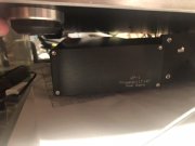
Got that.
It enters in the corner of the main box. The connection and filter board are within a faraday cage:
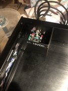
Then to the power switch- I decouple +, - and ground, as well as the feed for the LED all at once.
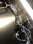
That litz braided line makes its way to the MM and then MC boards.
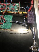
Lots more tidying to do but I deliberately have the MC board as far as possible from the incoming power. All the switching mombo-jumbo happens after signal is brought up to line level. Input wires are as short as possible. All signal wire is solid copper, tin plated. (Power is stranded, tin plated)
If I make this a product, as I hope to do, there will be one board with one power entry point and all switches mounted direct to the board. It’ll still be cramped around the op amps because you want those caps as close as possible. Otherwise I’m going to spread it out.
MAYBE some easier loading options. Possibly stealing the 47k idea of jumpers to set loading (and gain in the case of the 47k). The board designer is quite busy but he did get me files for the elliptical filter. That’s a much easier project. Besides the filter, it will also have switchable 10dB gain.

Got that.
It enters in the corner of the main box. The connection and filter board are within a faraday cage:

Then to the power switch- I decouple +, - and ground, as well as the feed for the LED all at once.

That litz braided line makes its way to the MM and then MC boards.

Lots more tidying to do but I deliberately have the MC board as far as possible from the incoming power. All the switching mombo-jumbo happens after signal is brought up to line level. Input wires are as short as possible. All signal wire is solid copper, tin plated. (Power is stranded, tin plated)
If I make this a product, as I hope to do, there will be one board with one power entry point and all switches mounted direct to the board. It’ll still be cramped around the op amps because you want those caps as close as possible. Otherwise I’m going to spread it out.
MAYBE some easier loading options. Possibly stealing the 47k idea of jumpers to set loading (and gain in the case of the 47k). The board designer is quite busy but he did get me files for the elliptical filter. That’s a much easier project. Besides the filter, it will also have switchable 10dB gain.
- Joined
- Nov 15, 2021
- Messages
- 482
- Location
- near Liverpool, NY
- Tagline
- Lifelong student / listening = bliss
J!m,
I was drooling over the photos & your writeup. I like the layout, the wiring is first rate, and even the details like the Nyloc nuts are superb!
The level that you guys are working at is both humbling & inspirational! I am feeling the burn...in a good (motivational) way! Yet again I find myself writing that you are already at where I am headed. (!)
Looking forward to your report on what it sounds like after it breaks in...
Nice job - Respect!
Last edited:
- Joined
- Nov 15, 2021
- Messages
- 482
- Location
- near Liverpool, NY
- Tagline
- Lifelong student / listening = bliss
View attachment 60437
Arrow (1) shows what the claimed 50 dB signal/noise ratio of a new board with the stock components to give you a visual perspective.
Arrow (2) is showing the theoretical dynamic range improvement available if a perfectly stable 9V power is fed to our (4) transistors on the board. Of course the way I drew it could make one think that I'm saying that there would be more gain from the circuit at all times, even with a steady-state test tone. I am not saying that. Instead, I am trying to fix the 9v power 'bouncing' underneath our active devices during transient demands.
First off, let's assume that we are determined to stay with the cigarette case & 9V battery form factor. Period. OK then, with that decision made then this graph showing various 9v batteries being discharged at a 100mA/hour rate will help set our "transient current delivery" performance expectations:
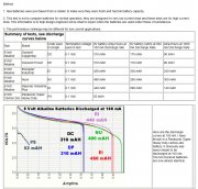
(For 2 more graphs showing 500mA/hr & 1 amp/hr discharge curves + good explanation go to this website.)
So, given this info, if C11 is sized optimally all we care about is the total power (amount of mAH) that each battery will give us. In terms of name-brand batteries, it looks like the Energizer Industrial has the most to share. (Don't know if it also wins the $/mAH metric.)
Another safe bet is that *if* C11 is undersized, then the old-school Panasonic Carbon-Zinc battery might make itself audible at the peaks given that it wasn't designed to deliver large amounts of instantaneous current. (!) Maybe audible, maybe not. But we can say that not all 9v batteries are the same under load. (!)
****
But then I read that the inside of a 9v battery is actually (6) diminutive 1.5v cells in series. So that made me think of the PhD with the (16) alkaline D-cells inside. Hmmm...I wonder if (6) x 1.5v D-cells would be able to provide more amperage oomph...to further stiffen the 9v traces during music transients/better recharge C11 between music transients?
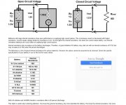
(taken from this site - go here for a good explanation about the internal resistance of batteries.)
As battery-powered phono circuit hot-rodders the 'Internal Resistance chart' is *exactly* what we have been scouring the internet for! Check out the internal resistance of a rechargeable D-cell NiCad vs a 9v alkaline!
That is a huge difference. But here's the rub. If the internal resistance of our batteries stayed the same across the range of 20hz-20Khz, then we would be all set. Guess what? Because we are dealing with *music*, when we are told that as the frequency of the demand goes up, but the chemical reactions feeding the current flow into the circuit continues at the same rate -- then we actually find ourselves discussing the effective impedance of a DC battery trying to keep up with high frequency AC demands. (Think Kraftwerk. :0)
The good news for us is that with the addition of C11 on the board, we can support both low & high frequency demands no problem...especially if the capacitor we install has a good ESR (Equivalent Series Resistance) rating. ...more on that in a follow-on post.
****
Given *my* priorities with this preamp -- keeping it cigarette-pack sized so I can tuck this into my shirt pocket (0) versus what it actually
sounds like in my main system (100) ...I'm pretty sure that I am going to upsize the case for this preamp, install (6) rechargeable NiCad batteries, feeding into an optimally-sized tested-good C11 'transient load decoupling' capacitor, and by doing this I will give the active devices in my preamp a rock-solid 9v platform to work with. And as long as I remember to power off the preamp between listening sessions, recharging intervals should be well below my threshold of pain. :0)
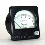
(Maybe install an old-school voltmeter that is out of circuit unless I depress the 'Push to Test' button? No pulling the batteries too soon...plus I like gauges... :0)
That's all I've got to say about the proposed DC power subsystem.
3D gump
Last edited:
- Joined
- May 1, 2013
- Messages
- 7,399
- Location
- Australia
- Tagline
- Those who enter the man cave will get WOPLed
There is some great info there, very interesting read (yes my dinner went cold), really appreciate the contributions too!
Still waiting for the other 3 battery pre's to show up, great idea about using 2 in stock form. What will be more interesting is applying the mods and listening. 3D you are going into a lot of detail here, good stuff.
Still waiting for the other 3 battery pre's to show up, great idea about using 2 in stock form. What will be more interesting is applying the mods and listening. 3D you are going into a lot of detail here, good stuff.
- Joined
- Nov 15, 2021
- Messages
- 482
- Location
- near Liverpool, NY
- Tagline
- Lifelong student / listening = bliss
There is some great info there, very interesting read (yes my dinner went cold), really appreciate the contributions too!
Still waiting for the other 3 battery pre's to show up, great idea about using 2 in stock form. What will be more interesting is applying the mods and listening. 3D you are going into a lot of detail here, good stuff.
Still waiting for the other 3 battery pre's to show up, great idea about using 2 in stock form. What will be more interesting is applying the mods and listening. 3D you are going into a lot of detail here, good stuff.
I pride myself on an open mind. I've learned something from every car I've ever ridden in, no matter how new or old, fast or slow, road course rocket or rusted out sh!tbox. Same thing with computer systems, photography, or audio systems. So, if somebody said that they got a new battery-powered preamp for their main system and you should hear how quiet it is -- you can bet that I'm going to hotfoot it over there with my favorite tunes & listen all the way to the bottom of the grooves... :0)
...but I digress. In so many of the other forums people seem to shed much more heat than light on any given subject...which explains why I was read-only in those other web sites. But the vibe here is different -- feels more like people are congregating here to help each other with their stuff -- much like in the old days when farmers would help each other with barn-raising.
Back to these little pre-amps. Sure, I am curious as to what the end result is going to sound like...but I've got a lot to learn/relearn, and fortunately for me this preamp is very simple & finite, so I have no excuse to not learn what every single component contributes to the overall sonic performance. And after a lot of hands-on experimentation & I really have a feel for the circuit, *then* I want to use this analog phono circuit I finally comprehend as a building block to learn SPICE with. (Instead of trying to learn a new circuit + SPICE simultaneously - that's too much at once.)
I want to make controlled changes to the module, and see if I can document with test equipment any audible differences I generate. I'm also a big believer in min-max testing -- that is, deliberately make one part of a circuit worse *before* I try to make it better...just so that I can listen to the culmulative changes, allowing me to better understand exactly how it sounds when it's wrong. (For future troubleshooting.)
Just like the first time you overdo it by twisting the distributor too far and over-advancing the timing, thinking this is the hot setup...and then driving the car down the road with the engine pinging/detonating...and the starter will now barely turn the engine over. That is a learning experience that proves to be invaluable when troubleshooting, even years later.
When I was young I would make mistakes, get mad about it, not realizing how much more you learn when this happens.
Now, I make mistakes on purpose, just to make sure that I really comprehend how the system does / does not work.
You know, I always wondered what it was going to be like to get old. And the young me would have never, ever guessed that the old me would go out of his way to get stuff wrong...just so I can test my overall comprehension for completeness.
Huh?
:0)
Anyway, glad my power subsystem musings were interesting enough that your dinner went cold! :0)
Be sure to let us know when your preamps show up & what differences (if any) you can pick out of the mix when you get a chance to audition the Rat Shack Dual Mono listening experience. And don't forget to have fun while experimenting!
Cheers --
Last edited:
- Joined
- May 1, 2013
- Messages
- 7,399
- Location
- Australia
- Tagline
- Those who enter the man cave will get WOPLed
When I was young I would make mistakes, get mad about it, not realizing how much more you learn when this happens.
- Joined
- Nov 15, 2021
- Messages
- 482
- Location
- near Liverpool, NY
- Tagline
- Lifelong student / listening = bliss
So, it sounds better to have delicate signals from a moving coil going into an unshielded plastic box?
Im an idiot but I’ve gotta call bullshit on that.
Im an idiot but I’ve gotta call bullshit on that.
Last night when I crossed the Rubicon and decided to go with a larger physical enclosure (freeing up my choices in batteries, caps, etc) I neglected to mention that (given my preoccupation with RFI shielding) my plan was to line the inside of the cigar box with copper screen. Since this is a performance-oriented project, if the cigar carton becomes the final enclosure choice, then I will cheerfully spend the extra $$ to make Faraday proud.
(Hey, a project isn't a real project...until there's a little project creep to complain about. :0)
That's all for now.
3D
PS - I really did like the way you fully shielded the space where the power came into your preamp. You can't be too careful with all things involving power... :0)
Last edited:

