Offset is positive or negative on the RevE and G1 depending on the offset of the FET input of the OPA134. There is no typical direction for it. Rev D and earlier typically had negative offset voltage due to the NPN bipolar input stage it employed

You are using an out of date browser. It may not display this or other websites correctly.
You should upgrade or use an alternative browser.
You should upgrade or use an alternative browser.
PL 700 Pro Build
- Thread starter George S.
- Start date
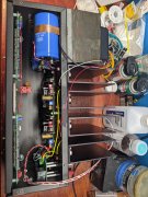
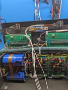
So look at all that room. Going to get some longer standoffs and space that control board away from the back planes a little more like Glen does his.
Going to lay a towel over the transformer and fins, lay the intermediate plate on it, and start wiring it.
Going to lay a towel over the transformer and fins, lay the intermediate plate on it, and start wiring it.
Attachments
Last edited:
- Joined
- Jan 14, 2011
- Messages
- 75,921
- Location
- Gillette, Wyo.
- Tagline
- Halfbiass...Electron Herder and Backass Woof
Join the club George..
wattsabundant
Chief Journeyman
Hi George
...The transformer bell can be connected to the transformer laminations. No problem with that. The through bolts must be isolated from the transformer core and end bell since the lines of flux cut through the bolts in normal operation and produce eddy currents in the bolts. The bolts also have to be isolated from the chassis. The transformer laminations and cradle can likewise be connected together and to the chassis. Just the bolts have to be isolated.
I just finished up a 400 with all of the goodies. Getting the transformer isolated was a challenge. I first tried heat shrink, which, to no surprise was too thick. I considered #12 screws and metric alternatives. While staring at the wall it hit me. Packing tape! The standard packing tape is a 1 7/8" wide. Here's the procedure.
1. Take a piece of packing tape about 8" long and lay it down on a bench, adhesive side up. Make sure the cut end is square.
2. Lay the bolt down parallel to the tape with the head against the edge of the tape.
3. Carefully roll it up like a joint. No wrinkles.
4. About 3/16" from the end use a knife to go around the bolt to cut the tape.
5. Grab the waste tape and pull it off the bolt.
The image below with the blue Sharpie ink was done to show the end of the tape on the threads. You can not see the end of the tape next to the head, but it does go right up to the head.
This technique provides about 3 layers of tape around the bolt. Before inserting the bolt in the transformer I pushed a 1/4" wooden dowel rod through the core to clean out any debris. If the tape is rolled up right it will go through with little resistance. Patience is a necessity. I had at least 10 failed attempts before all 4 bolts were wrapped. I used M8 nylon washers for isolation on each end of the bolt. I used flange nuts as seen in the last image.
Resistance readings from the bolts to the chassis and core were infinite. I would liked to have done a hipot test of 500 volts or so but lacked a safe way to do it.


![IMG_3820[1].JPG](https://forums.phxaudiotape.com/data/attachments/56/56406-079ba9d4e4917d491e14db51e595d0fc.jpg?hash=B5up1OSRfU "IMG_3820[1].JPG")
Good idea Don. The 700s are easy because a McDonalds straw fits them nicely, the 400s, not so easy with the smaller diameter bolt.I just finished up a 400 with all of the goodies. Getting the transformer isolated was a challenge. I first tried heat shrink, which, to no surprise was too thick. I considered #12 screws and metric alternatives. While staring at the wall it hit me. Packing tape! The standard packing tape is a 1 7/8" wide. Here's the procedure.
1. Take a piece of packing tape about 8" long and lay it down on a bench, adhesive side up. Make sure the cut end is square.
2. Lay the bolt down parallel to the tape with the head against the edge of the tape.
3. Carefully roll it up like a joint. No wrinkles.
4. About 3/16" from the end use a knife to go around the bolt to cut the tape.
5. Grab the waste tape and pull it off the bolt.
The image below with the blue Sharpie ink was done to show the end of the tape on the threads. You can not see the end of the tape next to the head, but it does go right up to the head.
This technique provides about 3 layers of tape around the bolt. Before inserting the bolt in the transformer I pushed a 1/4" wooden dowel rod through the core to clean out any debris. If the tape is rolled up right it will go through with little resistance. Patience is a necessity. I had at least 10 failed attempts before all 4 bolts were wrapped. I used M8 nylon washers for isolation on each end of the bolt. I used flange nuts as seen in the last image.
Resistance readings from the bolts to the chassis and core were infinite. I would liked to have done a hipot test of 500 volts or so but lacked a safe way to do it.
View attachment 59649View attachment 59651View attachment 59653View attachment 59654View attachment 59655View attachment 59656View attachment 59658
That ultra thin plastic heat shrink that they use for battery packs would likely work OK too. Have not tried that or tried to locate it but there are many sellers of that stuff out there.
Great idea Don! My 400 S2 was TIGHT, the S1 less so.I just finished up a 400 with all of the goodies. Getting the transformer isolated was a challenge. I first tried heat shrink, which, to no surprise was too thick. I considered #12 screws and metric alternatives. While staring at the wall it hit me. Packing tape! The standard packing tape is a 1 7/8" wide. Here's the procedure.
1. Take a piece of packing tape about 8" long and lay it down on a bench, adhesive side up. Make sure the cut end is square.
2. Lay the bolt down parallel to the tape with the head against the edge of the tape.
3. Carefully roll it up like a joint. No wrinkles.
4. About 3/16" from the end use a knife to go around the bolt to cut the tape.
5. Grab the waste tape and pull it off the bolt.
The image below with the blue Sharpie ink was done to show the end of the tape on the threads. You can not see the end of the tape next to the head, but it does go right up to the head.
This technique provides about 3 layers of tape around the bolt. Before inserting the bolt in the transformer I pushed a 1/4" wooden dowel rod through the core to clean out any debris. If the tape is rolled up right it will go through with little resistance. Patience is a necessity. I had at least 10 failed attempts before all 4 bolts were wrapped. I used M8 nylon washers for isolation on each end of the bolt. I used flange nuts as seen in the last image.
Resistance readings from the bolts to the chassis and core were infinite. I would liked to have done a hipot test of 500 volts or so but lacked a safe way to do it.
View attachment 59649View attachment 59651View attachment 59653View attachment 59654View attachment 59655View attachment 59656View attachment 59658
Don, your idea is going to help a lot of people.I just finished up a 400 with all of the goodies. Getting the transformer isolated was a challenge. I first tried heat shrink, which, to no surprise was too thick. I considered #12 screws and metric alternatives. While staring at the wall it hit me. Packing tape! The standard packing tape is a 1 7/8" wide. Here's the procedure.
1. Take a piece of packing tape about 8" long and lay it down on a bench, adhesive side up. Make sure the cut end is square.
2. Lay the bolt down parallel to the tape with the head against the edge of the tape.
3. Carefully roll it up like a joint. No wrinkles.
4. About 3/16" from the end use a knife to go around the bolt to cut the tape.
5. Grab the waste tape and pull it off the bolt.
The image below with the blue Sharpie ink was done to show the end of the tape on the threads. You can not see the end of the tape next to the head, but it does go right up to the head.
This technique provides about 3 layers of tape around the bolt. Before inserting the bolt in the transformer I pushed a 1/4" wooden dowel rod through the core to clean out any debris. If the tape is rolled up right it will go through with little resistance. Patience is a necessity. I had at least 10 failed attempts before all 4 bolts were wrapped. I used M8 nylon washers for isolation on each end of the bolt. I used flange nuts as seen in the last image.
Resistance readings from the bolts to the chassis and core were infinite. I would liked to have done a hipot test of 500 volts or so but lacked a safe way to do it.
View attachment 59649View attachment 59651View attachment 59653View attachment 59654View attachment 59655View attachment 59656View attachment 59658
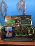
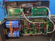
Making progress. The power switch was factory wired to use both sets of contacts with two buss wire jumpers on the bottom of the switch.
Decided to dress the full length of all control board wiring since I have plenty of that 1 MM sheathing. I do miss seeing the cool rainbow colors. Time to break and get away from this for awhile.
Decided to dress the full length of all control board wiring since I have plenty of that 1 MM sheathing. I do miss seeing the cool rainbow colors. Time to break and get away from this for awhile.
Attachments

derek92994
Veteran and General Yakker
VRLA's (valve regulated lead acid) are notorious for thermal runaway. I had a set do that in our battery lab a few months ago. The valve opened on a couple cells and spewed like a geyser. Stunk up the building. Fortunately the rack is on a concrete floor.
Following your advice, I will keep the batteries as a backup to run the fridge and lights only, they are almost at end of life and have done a lot of charge cycles. Power failures are not common here, but its handy to have a backup when they do occur. Lucky nothing bad has happened during charging as they would charge on a timer when I was at work. Now I know the potential of thermal runaway, I can be more careful about it.
I am going to stick to running the stereo setup of that dedicated 15 amp circuit and furman power conditioner. Is there any potential issues that could arise running the preamp and other components off the same circuit, or should they be separated?
Belden 83284 coax. The outer insulation can be carefully stripped with a razor blade, then the woven braid teased apart with a pointed Xacto blade.
https://catalog.belden.com/index.cfm?event=pd&p=PF_83284&tab=downloads
https://catalog.belden.com/index.cfm?event=pd&p=PF_83284&tab=downloads
Attachments
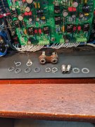
Hmmm, so I have a question I should have asked prior to starting the attenuators.
This amp has 50k ohm pots. My other WOPLs have 100k.
So if I understand the wiring correctly, the preamp should see the entire value of the pot at all times. And of course attenuation changes the value at the amp, but not the value that the preamp sees.
If I have this correct so far, do I need to pull those 50k and replace with 100k?
I do have 4 of the 100k Bourns Pro Audio grade pots if need be.
Thanks all, should have asked this weeks ago.
Hmmm, so I have a question I should have asked prior to starting the attenuators.
This amp has 50k ohm pots. My other WOPLs have 100k.
So if I understand the wiring correctly, the preamp should see the entire value of the pot at all times. And of course attenuation changes the value at the amp, but not the value that the preamp sees.
If I have this correct so far, do I need to pull those 50k and replace with 100k?
I do have 4 of the 100k Bourns Pro Audio grade pots if need be.
Thanks all, should have asked this weeks ago.
I personally like no pots at all (like the original PL400) because they just add noise and variable phase lag conditions when the pot interacts with the input filter cap of 220pF. If you have to have pots, I prefer 50K, my preamp has an output impedance below 50 ohms so it really doesn't care what it is driving. PL chose 100K likely to allow it to be driven by high impedance tube preamps.
Joe, thanks for your thoughts and insight. I'm going to go with the original 50k pots in the 700. If I have issues in a triamp setup with gain, I'll convert the 400s from 100k to 50k. Thanks again.I personally like no pots at all (like the original PL400) because they just add noise and variable phase lag conditions when the pot interacts with the input filter cap of 220pF. If you have to have pots, I prefer 50K, my preamp has an output impedance below 50 ohms so it really doesn't care what it is driving. PL chose 100K likely to allow it to be driven by high impedance tube preamps.
Last edited:
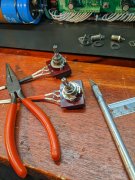
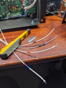
When I WOPLed my two 400s, wiring the attenuators confused the hell out of me. I really didn't understand which end of the coax should go to the control board or RCA jack and why.
Mark Comer made a post last year explaining it in terms I understood. Basically the preamp should not see a change of resistance when the pot is turned. So put the ohm meter between the shield and each center conductor of the each channels coax and turn the pot. The unchanging value should be very close to the pots value, and this coax gets wired to the RCA jack input from the preamp. The ohm reading on the other coax will change from close to zero to close to the value of the pot. This coax goes to the respective channels connection on the control board. Yeah, it's simple, but I didn't understand until Mark C. explained it. Thanks Mark!
I use small pieces of heat shrink to keep the channels straight. The blue shrink designates RCA connection.
Attachments
Last edited:
grapplesaw
Veteran and General Yakker
George can you post the link to this thread your are referring toWhen I WOPLed my two 400s, wiring the attenuators confused the hell out of me. I really didn't understand which end of the coax should go to the control board or RCA jack and why.
Mark Comer made a post last year explaining it in terms I understood. Basically the preamp should not see a change of resistance when the pot is turned. So put the ohm meter between the shield and each center conductor of the each channels coax and turn the pot. The unchanging value should be very close to the pots value, and this coax gets wired to the RCA jack input from the preamp. The ohm reading on the other coax will change from close to zero to close to the value of the pot. This coax goes to the respective channels connection on the control board. Yeah, it's simple, but I didn't understand until Mark C. explained it. Thanks Mark!
I use small pieces of heat shrink to keep the channels straight. The blue shrink designates RCA connection.
thanks