My Father's Continuing Saga........

Joined
May 26, 2013
Messages
713
Location
St. Louis, MO.
Tagline
Born and Raised In The 700 Watt Club.
Nice! did you sorce it from Mouser or have a nice stash of resistors
Here is a photo of my storage capacitor discharge resistor with the clips and one of the resistors that go across the output jacks when setting the bias. I misplaced the 2nd and need to find it. Make a nice discharge resistor jumper as you'll be using it over and over. Just clip it on and wait a few minutes. That resistor will get warm, cool off, done, discharged.
Awesome. I went ahead and ordered the resistors and a bunch of fuses. Gonna be about Jan 12-14th to get everything so I guess Installing transistors will have to wait a while. I don't just have random parts like that lying around. So I can probably do the smoke test with as far as I have gotten but that's about it. 50/50 shot it doesn't blow up! :p
 

George S.

Veteran and General Yakker
Joined
Feb 18, 2020
Messages
5,034
Nice! did you sorce it from Mouser or have a nice stash of resistors


Awesome. I went ahead and ordered the resistors and a bunch of fuses. Gonna be about Jan 12-14th to get everything so I guess Installing transistors will have to wait a while. I don't just have random parts like that lying around. So I can probably do the smoke test with as far as I have gotten but that's about it. 50/50 shot it doesn't blow up! :p
No, really had no parts prior to getting interested in WOPLs, recapped monitor power supplies and computer motherboards as needed here at the house is all. Once I decided to build the amps I took my time just like you are. Your doing a great job! Later.
 
Joined
May 26, 2013
Messages
713
Location
St. Louis, MO.
Tagline
Born and Raised In The 700 Watt Club.
Thanks George!

I spoke with my brother yesterday, and told me my father said when he gets this back from me; he's taking it outside in the backyard with an extension cord before applying power. Guess he wants to keep the mushroom cloud within the confines of the outdoors! LOL! :eek:
 

mlucitt

Veteran and General Yakker
Joined
Jun 24, 2011
Messages
3,494
Location
Jacksonville, FL
It even graciously includes ground wire if you use Don's DC Protect board.
There are nine ground wires connected to the Star ground in my amplifier builds. As follows (all gray except #8):
1. L Backplane GND1
2. L Backplane GND2
3. R Backplane GND1
4. R Backplane GND2
5. L Speaker Ground
6. R Speaker Ground
7. DCP Ground
8. Chassis Single Point Ground (white)
9. LED/Meter Board Ground

Of course, you are free to wire the amp any way you want including the ground scheme. Everybody has their preferences.
 
Joined
May 26, 2013
Messages
713
Location
St. Louis, MO.
Tagline
Born and Raised In The 700 Watt Club.
There are nine ground wires connected to the Star ground in my amplifier builds. As follows (all gray except #8):
1. L Backplane GND1
2. L Backplane GND2
3. R Backplane GND1
4. R Backplane GND2
5. L Speaker Ground
6. R Speaker Ground
7. DCP Ground
8. Chassis Single Point Ground (white)
9. LED/Meter Board Ground

Of course, you are free to wire the amp any way you want including the ground scheme. Everybody has their preferences.
That's exactly what I have, and almost exactly the same colors. Except I made #7 and #9 Black because either that's what comes with the kit or that's what Joe's instructions say to use. I also prefer to leave the two speaker grounds a different color than DCP ground since they are on the same board even though potential is the same. L/R speaker is one "type", Ground is another "type".

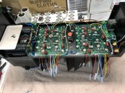
After everything had been alchoholed to death, compressed aired, and chassis ring out check fives times; it was time to do the power up. Last night with a few assurances I was doing it right from Lee; I went ahead and brought up the amp on the variac and DBT. Relay 'clicked', smelled no smoke; kept on goin. At 120VAC still no smoke, everything looked solid. (whew) felt better that all that work passed the smell tests. Brought it back down; heard the relay click again, and unplugged it. Lee had the great idea of using the DBT as a resistor. Since I don't have the 200ohm, 5W here. Discharged the caps that way by hooking the prongs up with alligator clips to the caps and star ground. Never thought of that. Genius I say!

But twas late so didn't proceed any further. Today I will put the next row in, wash-rinse-repeat. Then hit up the driver board at the need and make my connections there. Set Bias. and call it stopped. -I can't go any farther until I receive that light board. Shipped Dec 6th. So I just may hook the old board back up so I can actually test the amp under a load. Otherwise I could be waiting until doomsday with USPS. And I just don't have the time after this holiday weekend is over. It's back to 72hrs a week working.

Anyway, out to do the next row................

IMG_3887.JPG
 

laatsch55

Administrator,
Staff member
Joined
Jan 14, 2011
Messages
74,914
Location
Gillette, Wyo.
Tagline
Halfbiass...Electron Herder and Backass Woof
Damn sure don't need stinking the light board to load that puppy... hell, I ran The Pig for weeks without one..
 
Last edited:

Gepetto

Administrator
Staff member
Joined
May 15, 2011
Messages
14,042
Location
Sterling, MA
Tagline
Old 'Arn Enthusiast
That's exactly what I have, and almost exactly the same colors. Except I made #7 and #9 Black because either that's what comes with the kit or that's what Joe's instructions say to use. I also prefer to leave the two speaker grounds a different color than DCP ground since they are on the same board even though potential is the same. L/R speaker is one "type", Ground is another "type".

After everything had been alchoholed to death, compressed aired, and chassis ring out check fives times; it was time to do the power up. Last night with a few assurances I was doing it right from Lee; I went ahead and brought up the amp on the variac and DBT. Relay 'clicked', smelled no smoke; kept on goin. At 120VAC still no smoke, everything looked solid. (whew) felt better that all that work passed the smell tests. Brought it back down; heard the relay click again, and unplugged it. Lee had the great idea of using the DBT as a resistor. Since I don't have the 200ohm, 5W here. Discharged the caps that way by hooking the prongs up with alligator clips to the caps and star ground. Never thought of that. Genius I say!

But twas late so didn't proceed any further. Today I will put the next row in, wash-rinse-repeat. Then hit up the driver board at the need and make my connections there. Set Bias. and call it stopped. -I can't go any farther until I receive that light board. Shipped Dec 6th. So I just may hook the old board back up so I can actually test the amp under a load. Otherwise I could be waiting until doomsday with USPS. And I just don't have the time after this holiday weekend is over. It's back to 72hrs a week working.

Anyway, out to do the next row................

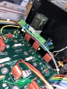
View attachment 47033
Hi Dave
I recommend you lace your DC runs separate from the AC runs on the upper edge of the amp. Tie your AC which goes to the thermal switch to the upper control board support close to the chassis back wall. Tie the DC runs all together and stand up and away from the AC run. That bundle will be stiff enough to be free standing.
 
Joined
May 26, 2013
Messages
713
Location
St. Louis, MO.
Tagline
Born and Raised In The 700 Watt Club.
Just spent the last hour on the phone with my father, giving him the update. He's def interested on hearing how it SOUNDS. His weak link right now is his Pre-amp. He isn't sold on Rotel anymore. He says they've
seemed to have taken a nose-dive in recent years. Didn't Marantz buy them out or something? Can't remember. He says the mids and high's are way too harsh. He's been eying up some Audio Research Sp-somethings on the bay, but doesn't want to get it, and you know the bay...."No returns, no takebacks". I said buy NEW. He said "Oh yeah!! The new one right now is Ten Thousand Dollars." Literally. So that's out.

Thanks Joe. I like the DC Board up there much better too. Glad we are going that route now.

Got all the transistors in. Nothing rang out to chassis ground. Tested that three times on each row. I am testing again and again and again, taking my time. I have a pile of Joes Instructions printed out all over the floor behind me I've been using as I go. There's a lot there. Working on the Control board now.....

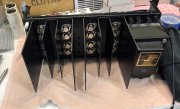
IMG_3890.JPG
 
Joined
May 26, 2013
Messages
713
Location
St. Louis, MO.
Tagline
Born and Raised In The 700 Watt Club.
He wants to watch the meters dance!
That's EXACTLY why. It's the last test on my list to make sure I didn't mis-wire the meter wires. (Though I don't see how), but hell...you never know.

My dad said "Your board is lost". I said "probably", but your Birthday is in March right? Gives me enough time to get a new one from Joe if I 'MUST'.......... :rolleyes:
 
Joined
May 26, 2013
Messages
713
Location
St. Louis, MO.
Tagline
Born and Raised In The 700 Watt Club.
Hi Dave
I recommend you lace your DC runs separate from the AC runs on the upper edge of the amp. Tie your AC which goes to the thermal switch to the upper control board support close to the chassis back wall. Tie the DC runs all together and stand up and away from the AC run. That bundle will be stiff enough to be free standing.
Will do! Sorry. I guess that got lost in the shuffle. Working on it as we speak. :)
 

laatsch55

Administrator,
Staff member
Joined
Jan 14, 2011
Messages
74,914
Location
Gillette, Wyo.
Tagline
Halfbiass...Electron Herder and Backass Woof
Dave. Have him check out the Acurus pre's..RL 11's relatively cheap and sounded almost as good as my Rowland...
 
Last edited:

wattsabundant

Chief Journeyman
Joined
Apr 26, 2011
Messages
934
Location
Central Ohio
That's exactly what I have, and almost exactly the same colors. Except I made #7 and #9 Black because either that's what comes with the kit or that's what Joe's instructions say to use. I also prefer to leave the two speaker grounds a different color than DCP ground since they are on the same board even though potential is the same. L/R speaker is one "type", Ground is another "type".

After everything had been alchoholed to death, compressed aired, and chassis ring out check fives times; it was time to do the power up. Last night with a few assurances I was doing it right from Lee; I went ahead and brought up the amp on the variac and DBT. Relay 'clicked', smelled no smoke; kept on goin. At 120VAC still no smoke, everything looked solid. (whew) felt better that all that work passed the smell tests. Brought it back down; heard the relay click again, and unplugged it. Lee had the great idea of using the DBT as a resistor. Since I don't have the 200ohm, 5W here. Discharged the caps that way by hooking the prongs up with alligator clips to the caps and star ground. Never thought of that. Genius I say!

But twas late so didn't proceed any further. Today I will put the next row in, wash-rinse-repeat. Then hit up the driver board at the need and make my connections there. Set Bias. and call it stopped. -I can't go any farther until I receive that light board. Shipped Dec 6th. So I just may hook the old board back up so I can actually test the amp under a load. Otherwise I could be waiting until doomsday with USPS. And I just don't have the time after this holiday weekend is over. It's back to 72hrs a week working.

Anyway, out to do the next row................

View attachment 47033
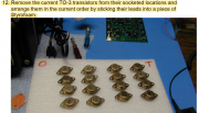
Hate to be a buzz kill, but, storing outputs in styrofoam seems like a good idea to protect the leads, but potentially exposes them to electrostatic discharge. Low probability. May take years to show up. ESD site
 
Joined
May 26, 2013
Messages
713
Location
St. Louis, MO.
Tagline
Born and Raised In The 700 Watt Club.
Hate to be a buzz kill, but, storing outputs in styrofoam seems like a good idea to protect the leads, but potentially exposes them to electrostatic discharge. Low probability. May take years to show up. ESD site
No you are looking at the OLD Transistors Don. They are getting TRASHED and going bye-bye!!

Besides, I believe I was just following the W.O. instructions per #12. I wouldn't know any different. It's one of the items on the "get" list and in part of the disassembly procedures.....

1609636404431.png
 

Attachments

Joined
May 26, 2013
Messages
713
Location
St. Louis, MO.
Tagline
Born and Raised In The 700 Watt Club.
Are those the 5/8" long standoffs? They look perfect in there!
I got these and used a nylon spacer with it. The standoffs screwed to the binding posts, and thus make contact with the board via the nuts on the top. It elevated them JUST perfectly. And it's nice and secure. Did a stress test by pushing the board around and was solid. If Don thinks that's a bad idea; I'll get the right length from him. He can chime in at any time. I'm open to doing what's right. :)

IMG_3903.JPG
 
Top