My Father's Continuing Saga........

Northwinds

Veteran and General Yakker
Joined
Mar 18, 2013
Messages
7,562
Location
Coventry, CT
Tagline
Fondler errrr... fan of all Nav's avatars
LOL, I wish I still had that pic of Blackie with the big box fan sitting on top of her. That was back when she was a Quasi and ran hot as hell but had dynamics that were more in your face then a FC! She had fuse issues also which Jer corrected and yes, the REAL Blackie resides behind the Silvara facelift. She never really left home, just went for plastic surgery :toothy5: and has a more refined sound
 
Last edited:

CASSETTE DECK

Chief Journeyman
Joined
Jun 20, 2013
Messages
696
Location
Kapiti Coast, New Zealand
Tagline
Path under Coastlands overbridge
Chris ya definitely want to kick that supply up to 120. Rails aint going to be up to where they need to be.
The speakers that I used in both tests couldn't handle the power, so I've been playing it safe.

1: Pioneer 6 ohm 70 watt. -- Used for the first test, initially with a 200 watt dim bulb tester.
2: JVC 4 ohm 140 watt -- I took these to their limit and burnt out the coils in the electromagnetic tweeters, but I fully expected that to happen. I've blown magnetic tweeters several times in the past. I have now converted these tweeters to piezo electrostatic.

I have plenty of step down transformers available that can deliver 120 volts at 2KVA or more including some 3KVA toroids, but I don't expect to be using these for a while, probably not until I have upgraded a pair of speakers and crossovers to to handle at least 250 watts RMS per channel.
 
Last edited:

jbeckva

Admin/Server Dude MAA Guy
Staff member
Joined
Jun 11, 2010
Messages
6,850
Location
Powhatan, Virginia, United States
Tagline
WassupYa Mang?
The speakers that I used in both tests couldn't handle the power, so I've been playing it safe.

1: Pioneer 6 ohm 70 watt. -- Used for the first test, initially with a 200 watt dim bulb tester.
2: JVC 4 ohm 140 watt -- I took these to their limit and burnt out the coils in the electromagnetic tweeters, but I fully expected that to happen. I've blown magnetic tweeters several times in the past. I have now converted these tweeters to piezo electrostatic.

I have plenty of step down transformers available that can deliver 120 volts at 2KVA or more including some 3KVA toroids, but I don't expect to be using these for a while, probably not until I have upgraded a pair of speakers and crossovers to to handle at least 250 watts RMS per channel.
That's cool.. but MAN... sure are a lot of turnit-uppit-itus folks 'round here LOL. I guess since I gots a grizzly bear downstairs I don't get to do that too much 'round here..

ey.. volume control.. your friend and good buddy... :toothy5:

heh.. Yep Ben, that was my first "experiment" in spray painting for a long time..
 

jbeckva

Admin/Server Dude MAA Guy
Staff member
Joined
Jun 11, 2010
Messages
6,850
Location
Powhatan, Virginia, United States
Tagline
WassupYa Mang?
paint job

Yeah, the black started out as a real nice piano gloss. Thing about it was I didn't let it dry long enough to do a good feather and recoat, so I ended up "brushing" it for that worn look (or at least something half decent). The gloss would have been real sharp!
 

BubbaH

Veteran and General Yakker
Joined
Mar 13, 2013
Messages
3,315
Tagline
---
I always liked the lettering on it. And I did love Ron's pic with the fan on it.
 
Joined
May 26, 2013
Messages
713
Location
St. Louis, MO.
Tagline
Born and Raised In The 700 Watt Club.
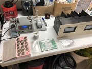
Alright, So my Father has Retired as of Dec 23rd. In his 70's now, the man has worked way longer than he should have. But work-aholics run in the family, I get it. Now he is ready to turn his attention BACK to speakers and amps and Vintage gear. I am continuing this thread where it left off because that's basically where HE left off. -Still uncertain about the PL gear and "Carver this" and Carver that". "They sound like Tube amps". But the man doesn't want to pay money to get a vintage piece of equipment to "Try Something Out" then ya can't send it back. So he's stuck only reading internet opinion pieces of the gear.

My Hope here, is to put this continuing saga to BED. Lord knows it's been going on for over a decade now. It's time to WHITE OAK this beyatch!
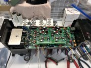
And what better opportunity than now, as fate would have put it; one of his four PL400's blew up and was blowing channel fuses. I decided I was going to overhaul it for him. I mean I can't break it anymore than it's already broken? CAN I?......

So two weeks ago I got all the W.O. parts I could think of and started looking my project in the face. He's had these things for 40 years and they have never been to an audio shop. He at one point replaced them sometime in the 90's with an Audio Research SP3 Pre-amp and an Audio Research D-70 something? Hell I can't remember. But in the late 2000's, he sold it off because he said it was getting too ridiculously expensive to replace the vacuum tubes. $800 per tube or something nutz! Back to the 400's he went. And since then he never really got over that "Tube Sound".

We tried introducing here in this thread, Jerry's amp, but in 2014, I think we only had the driver board RevB and the bulk caps at our disposal. He didn't really hear the difference vs cost-to-build thing. So back it went. Fast forward to TODAY and man things have changed. I will be updating this thread as I go. It's time to treat the man who raised me for half a century to a fine reward. His own WOPL. He never liked the sound of the PL700B's. Maaaybe he could tell but a slight difference in that the PL400 wasn't as "harsh" on the high end. Like Mark said somewhere else on this forum, It's getting to the point at this age where I can't tell the difference between the two. The golden ears in his golden years are starting to fade, but his listening tastes have become finer and even more specific. I hope this project helps him see that once you go WOPL, you never go back.

I still am not that confidant in my abilities, but I feel I have a better handle on it than I did 8 years ago. A lot of the tech-spec talk is over my head. I fully admit it. This will either be a great project or a WOPL Sniffer-type Mushroom Cloud! I am as Green at this as Joes Boards! So bear with me guys. I'll need your help. :help:
 
Last edited:
Joined
May 26, 2013
Messages
713
Location
St. Louis, MO.
Tagline
Born and Raised In The 700 Watt Club.
Just a walk in the park...
We'll help you get that amp going. Just be ready to take lots of pictures, most of us have fuzzy vision in our mind's eye.
:wwoutpics1:

Yeah I know. I have them, but I'm going to post in drips and drabs. Some people here don't like long paragraphs or explanations. I'll play catch up eventually. Can I ask the Moderators here to move this thread into the WOPL Building Category? That's what this thread has morphed into, rather than starting a new thread. Sometimes the tie-In backstory helps.

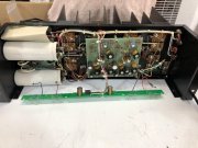
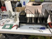
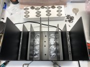
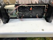
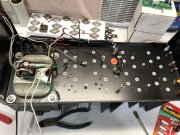
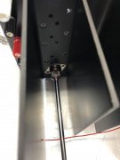
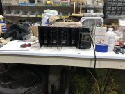
Started the tear down last week............

IMG_3765.JPG IMG_3768.JPG IMG_3783.JPG IMG_3784.JPG

IMG_3779.JPG

IMG_3781.JPG

IMG_3794.JPG
 
Joined
May 26, 2013
Messages
713
Location
St. Louis, MO.
Tagline
Born and Raised In The 700 Watt Club.
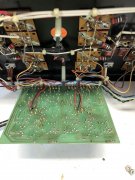
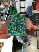
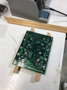
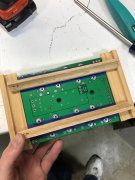
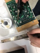
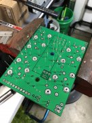
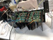
Got the assembly of the Backplanes Done the couple days after Christmas. In THIS particular instance; I had Joe assist me on the PEM Nuts. Since it's for my father and not a personal project; I want to make sure it's as successful as possible. And I can't thank him enough for the assist. Everything else was me. Unfortunately; one of the things I didn't consider was when he did them, it still meant I had to solder the solder cup sockets in and the PEMS wouldn't allow me to put the board FLAT on a surface to hold them in place while I did the work. So I had to find a creative solution to gain pressure on them while I did my work. I made a CRUDE Jig of sorts from some spare scrap wood I had lying around. Made it into a Tray with bars that would go between the PEM nuts. It worked! (whew) Cause that tape wasn't gonna cut it and I don't have a third hand.

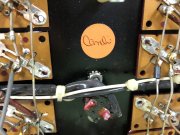
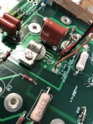
I made a small mistake with the bias transistors. I did those first without realizing that once the board went in; the standoffs would push the aluminum holders UP and well......my legs were too short because I thought the holder sat flat w/the board. So the legs wanted to twist sideways. Crap. In one of them it broke the legs. Well.....good thing I have a couple spare 2N5088's. Shitty part was I already used the super glue per instructions so knocking them out of the holders blew chunks. Once done; I went back to work. THIS time I put a nylon washer under it as I soldered the legs to the board. They acted as a temporary standoff height support while I did that. Grrr....live and learn right? That's WHY I wanted to do this. I can't learn shit if I don't eff something up myself. Some progress of that stage.............

IMG_3798.JPG

IMG_3800.JPG

IMG_3801.JPG

IMG_3805.JPG

IMG_3821.JPG

IMG_3817.JPG

IMG_3849.JPG

IMG_3826.JPG

IMG_3827.JPG
 
Joined
May 26, 2013
Messages
713
Location
St. Louis, MO.
Tagline
Born and Raised In The 700 Watt Club.
That has got to be the cleanest PL400 I have ever seen.
I think most of his amps are like this. They always sat 12-feet high on the top shelf for the last 40 years. No kids to get their grimey hands on them. LOL! -It also helps I alcoholed the snot out of the chassis before I started adding ANYTHING. No dang tiny miniscule solder blob's gonna get me THIS time!
 
Joined
May 26, 2013
Messages
713
Location
St. Louis, MO.
Tagline
Born and Raised In The 700 Watt Club.
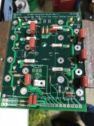
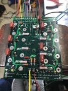
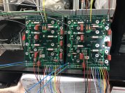
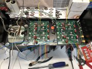
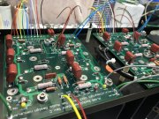
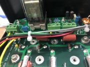
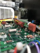
Monday evening; re-routed the thermal cutoff and power wiring. Added a new 30Amp Bridge Rectifier and snubber caps. Then replaced the speaker binding posts and RCA jacks. I put in the nylon shoulder washers and basically prepped for the boards going in. I added Joes boards and Don's DC Protect and went to work with the wire routing to neaten it up. I got the bottom row transistors installed, and added the caps. I dry-fit the driver board at the end to make sure I hadn't botched any clearance tolerances with my board population. I ran out of time and got far enough to run every wire I could think of over to the star ground. Tied em up and sat em there. Even the light board wire. That's next on the list this weekend before I can attempt even doing any power testing.

We have a rather snug fit at Don's DC Protect board shoving the Polypropylene caps on the right backplane board forward. The caps are kinda in the way of the DC protect wiring too. And the board bottomed out when it hit the top of the Manley RCA Jacks outter shell, so I'll be elevating that with some posts. I think Don will be including them in the PL400 kits now like he does with the 700's. I think it will look a lot neater and I can straighten out those caps.

So far that's where I stand right now with everything. Works been in the way. Here's the progress below:

IMG_3841.JPG

IMG_3843.JPG

IMG_3850.JPG

IMG_3852.JPG

IMG_3854.JPG

IMG_3855.JPG

IMG_3863.JPG

IMG_3864.JPG

IMG_3857.JPG
 

mlucitt

Veteran and General Yakker
Joined
Jun 24, 2011
Messages
3,495
Location
Jacksonville, FL
I really like those Manley RCA jacks, and the fit in the chassis holes is perfect. I got mine directly from EveAnna Manley.
The four 1 1/2" DCP extensions are Mouser P/N 534-2206.
Your solution for the Q115 bias transistors was the same as mine, I bend the legs without cutting them and kick them up real high, then when the P-strap is raised up, the legs flatten out.
 
Last edited:

Gepetto

Administrator
Staff member
Joined
May 15, 2011
Messages
14,057
Location
Sterling, MA
Tagline
Old 'Arn Enthusiast
I really like those Manley RCA jacks, and the fit in the chassis holes is perfect. I got mine directly from EveAnna Manley.
The four 1 1/2" DCP extensions are Mouser P/N 534-2206.
Your solution for the Q115 bias transistors was the same as mine, I bend the legs without cutting them and kick them up real high, then when the P-strap is raised up, the kegs flatten out.
Kegs! Huh??? I like the way you think Mark.
 
Top