A non-PL quasi-comp output transistor question

62vauxhall

Veteran and General Yakker
Joined
May 14, 2014
Messages
2,324
Location
Southwest Kootenays BC
Tagline
No such things as bad days, just bad moments
#1
Hoping for some general info concerning a dual mono Rotel RA-1412 integrated.

Both power supplies have been made to work but the Protection circuit will not disengage. Unless the left main amplifier board is disconnected.

As far as I have been able to tell, there is nothing wrong with that board. All components are good and nothing wrong on the trace side. And with the left channel main amplifer disconnected, the right channel works fine.

~60 volts exits the left main amp board at pin 5 to the Protection circuit when it's connected and it should be (near) zero as it is with the right main amplifier board.

All four output transistors were removed from the left channel thinking I could "trouble shoot" without them. Two are blown anyway but the other two are OK.

I am tempted to re-install the two good output transistors to see if that stops the ~60 volts exiting the left main amp board to the protection circuit. But I am unsure if the transistors need to be horizontal or vertical.
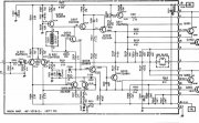
Rotel R1412 power amp schematic left.JPG
 

Gepetto

Administrator
Staff member
Joined
May 15, 2011
Messages
14,042
Location
Sterling, MA
Tagline
Old 'Arn Enthusiast
#2
I think I have to Huh!! this.

But I am unsure if the transistors need to be horizontal or vertical.

Also do you have a schematic without being cut off on the right hand side?
 

WOPL Sniffer

Veteran and General Yakker
Joined
Aug 10, 2015
Messages
11,522
Location
Minnie-Soda
Tagline
Screw it
#4
I think I have to Huh!! this.

But I am unsure if the transistors need to be horizontal or vertical.

Also do you have a schematic without being cut off on the right hand side?

Glad you did Joe, I scratched a hole in my head thinking about it. :)
 

WOPL Sniffer

Veteran and General Yakker
Joined
Aug 10, 2015
Messages
11,522
Location
Minnie-Soda
Tagline
Screw it
#5
Being the Output Transistors (2SD426?) are TO3 packages, I don't know what you mean by horizontal or vertical. They will only fit 1 way.
 

62vauxhall

Veteran and General Yakker
Joined
May 14, 2014
Messages
2,324
Location
Southwest Kootenays BC
Tagline
No such things as bad days, just bad moments
#6
Being the Output Transistors (2SD426?) are TO3 packages, I don't know what you mean by horizontal or vertical. They will only fit 1 way.
I was meaning the grouping of the transistors on the heatsink - corners of a square.

But I am usure if I install the two good transistors I have into either the top or bottom rows - what I meant by horizontal.
or
left or right columns - what I meant by vertical.

And yes, this amplifier did leave the factory with Toshiba 2SDA246 (TO3). Four per channel but at sometime two of those on the left side were replaced with Sylvania ECG-280's. The stock Toshibas are shot but the Sylvania's are OK. From what I read, they are the same transistor.

It would be the two Sylvania's I'd be using to see if the protection circuit stay's disengaged.

If I accomplish that, I would order new output transistors all around - eight of them. MJ15022 or MJ21194 - whichever I can get.
 

Gepetto

Administrator
Staff member
Joined
May 15, 2011
Messages
14,042
Location
Sterling, MA
Tagline
Old 'Arn Enthusiast
#10
One of your good outputs should go into Q001 and the other good one in Q003.

You only need 2 to bring the amp up, and check things out. You will need the other 2 for driving a full load.
 

62vauxhall

Veteran and General Yakker
Joined
May 14, 2014
Messages
2,324
Location
Southwest Kootenays BC
Tagline
No such things as bad days, just bad moments
#12
I would check or replace Q610. Is a 2SA814 available to you?
Q610 is not original. Someone at sometime put in a 2SB546A to replace the 2SA814. From what I understand, it is supposed to be an acceptible substitute. Some numbers on the datasheet make it look more rubust.

But just to make matters more difficult for myself, I broke the right channel's Q610 moments ago by manipulating it so I could read the number. So now I must find another replcacement for a 2SA814. From a brief search, an MJE15033 is supposed to work. And I happen to have one, and only one, of those on hand.


One of your good outputs should go into Q001 and the other good one in Q003.

You only need 2 to bring the amp up, and check things out. You will need the other 2 for driving a full load.
I tried that and it still goes into protection. But the voltage causing protection to activate did change. Went from (-)45 volts with no outputs installed to (-)35 volts with two outputs installed at Q001 & Q003.
 

Gepetto

Administrator
Staff member
Joined
May 15, 2011
Messages
14,042
Location
Sterling, MA
Tagline
Old 'Arn Enthusiast
#13
Do you follow what is going on in the circuit? Such that you can sleuth it out at various nodes to find out what is not functioning correctly?
 

Gepetto

Administrator
Staff member
Joined
May 15, 2011
Messages
14,042
Location
Sterling, MA
Tagline
Old 'Arn Enthusiast
#14
With your -35V on the output, you should report to us what the voltage readings are on the collector facing side of R606 and R610 are. We can take this step by step to see if we can find the culprit.

I would also then ask you to check the voltage you are seeing at the collector of the current source Q603 to see what you are getting there.
 
Last edited:

62vauxhall

Veteran and General Yakker
Joined
May 14, 2014
Messages
2,324
Location
Southwest Kootenays BC
Tagline
No such things as bad days, just bad moments
#15
The transistor I broke needs thermal paste, it's on a heatsink. I have some but it took a long time to find it. A while after I moved here, I organized all the various bits & pieces of stuff I brought along and had no clue what "logical place" I put it.

Tomorrow I'll install my substitute transistor and take those suggested readings.

Might not make any difference because it's not for the channel with the problem but I don't want to apply power until that wound has been healed.
 

wattsabundant

Chief Journeyman
Joined
Apr 26, 2011
Messages
934
Location
Central Ohio
#16
Are you using a light bulb in series with the line cord for testing? This prevents further damage. 35 volts suggests an issue in the front end. Check all transistor and diode junctions with a meter, on the diode function, with power turned off. Compare the readings with the other channel. For each test check the junctions with both polarities and write down the readings.

Referring to thermal paste, less is more. The paste serves only to fill in tiny air pockets between the two surfaces. When the transistor is installed the paste should not ooze out underneath the transistor. For TO3 outputs, a dot the size of a pencil eraser between the 2 pins is all that is needed. The die is located between the 2 pins. Silpads are preferred as they need no grease.
 

62vauxhall

Veteran and General Yakker
Joined
May 14, 2014
Messages
2,324
Location
Southwest Kootenays BC
Tagline
No such things as bad days, just bad moments
#17
With your -35V on the output, you should report to us what the voltage readings are on the collector facing side of R606 and R610 are. We can take this step by step to see if we can find the culprit.

I would also then ask you to check the voltage you are seeing at the collector of the current source Q603 to see what you are getting there.
Voltage at the collector ends of R606 & R610 is (-)47.
Voltage at the collector of Q603 is (+)48.
 

Gepetto

Administrator
Staff member
Joined
May 15, 2011
Messages
14,042
Location
Sterling, MA
Tagline
Old 'Arn Enthusiast
#18
Voltage at the collector ends of R606 & R610 is (-)47.
Voltage at the collector of Q603 is (+)48.
OK good that you have +48V at the collector of Q603. That is your high side drive. That 48V should be rippling through to the emitter of Q607 then Q609 losing a diode drop at each emitter. +48 then +47.3 at Q607 emitter and then 46.6V at the emitter of Q609. Are you getting those readings?
 

62vauxhall

Veteran and General Yakker
Joined
May 14, 2014
Messages
2,324
Location
Southwest Kootenays BC
Tagline
No such things as bad days, just bad moments
#19
OK good that you have +48V at the collector of Q603. That is your high side drive. That 48V should be rippling through to the emitter of Q607 then Q609 losing a diode drop at each emitter. +48 then +47.3 at Q607 emitter and then 46.6V at the emitter of Q609. Are you getting those readings?
Am using a DBT

No, the readings I got were:
Q607 Emitter - (-)34.0 volts
Q609 Emitter - (-)34.6 volts
 

wattsabundant

Chief Journeyman
Joined
Apr 26, 2011
Messages
934
Location
Central Ohio
#20
Direct coupled amplifiers such as this are difficult to troubleshoot by checking voltages. It's one big vicious circle with one stage feeding the next. That said, I would look at the base and emitter voltage readings of Q603 compared to the schematic. If that is OK then I would set the meter on the diode scale and look at the junctions of Q608 and then Q601, 602, 605, 606.

This amplifier doesn't have the traditional V/I limit protection circuits. Although I don't think it is the issue, the function of Q611 is interesting.

I used to do tech support over the phone with a lot of hand holding. It drove me crazy knowing that I could fix an issue if only I was in front of the system. Such is the case here. I feel I coule fix this one pretty quick if i had my hands on it. I'm reluctant to put in my 2 cents worth as it can quickly become "too many cooks in the kitchen." I never go to AK anymore for the same reason. The thought process there is buy the repair kit on EBAY and change out every transistor and diode. That's not troubleshooting, it's asking for more trouble.
 
Top