
You are using an out of date browser. It may not display this or other websites correctly.
You should upgrade or use an alternative browser.
You should upgrade or use an alternative browser.
Unwell Phase Linear 700 series II
- Thread starter Michael F
- Start date

WOPL Sniffer
Veteran and General Yakker
Michael F
Journeyman
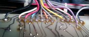
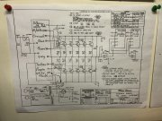
There seems to be a discrepancy between my control board and the manual. I have an extra wire (purple) on my board that doesn't correspond to what is on the manual. It`s right between the white/red striped wire and the input ground wires. That is the same on both Left and Right channels.
Attachments
grapplesaw
Veteran and General Yakker
Yes that is correctThere seems to be a discrepancy between my control board and the manual. I have an extra wire (purple) on my board that doesn't correspond to what is on the manual. It`s right between the white/red striped wire and the input ground wires. That is the same on both Left and Right channels.
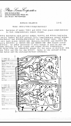
the manual is for quasi complimentary
Attached is service doc
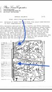
a new white wire goes to the old Violet and blue connection. The violet and blue reconnect to the transistor as on the attached
Attachments
grapplesaw
Veteran and General Yakker
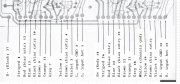
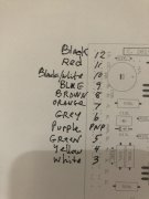
Here is connection for the color wires.There seems to be a discrepancy between my control board and the manual. I have an extra wire (purple) on my board that doesn't correspond to what is on the manual. It`s right between the white/red striped wire and the input ground wires. That is the same on both Left and Right channels.
Attachments

grapplesaw
Veteran and General Yakker
Here is connection for the color wires.There seems to be a discrepancy between my control board and the manual. I have an extra wire (purple) on my board that doesn't correspond to what is on the manual. It`s right between the white/red striped wire and the input ground wires. That is the same on both Left and Right channels.
Michael F
Journeyman
Thanks for that GrapplesawYes that is correct
the manual is for quasi complimentary
Attached is service doc
a new white wire goes to the old Violet and blue connection. The violet and blue reconnect to the transistor as on the attached
")
Now the only difference is the White/Red wires that I have and White only wire on the drawing, everything else seems ok.
Michael F
Journeyman
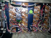
I`ve traced the wires that lead from the control board to the back planes; this is what I came up with going from left to right:
Left Channel
Black* B- fused
White/Red * NPN column output transistor Base buss
Red* Collector of bias transistor
Blue* Base of NPN column driver
Black* Base of Bias transistor
Brown* Emitter of bottom NPN column output transistor
Orange* Collector buss NPN column/fused B+
Grey* NPN and PNP output transistor common emitter point
Yellow* Emitter of bottom PNP output transistor
Brown* Emitter of bias transistor
White/Red * Collector buss of PNP column/Fused B-
Purple* Base of PNP column driver
Grey* Input ground
Black* Input signal
Right channel
Red* B+Fused
White/Red* Base buss NPN column
Red* Collector of Bias transistor
Blue* Base of NPN column driver transistor
Black* Base of Bias transistor
Brown* Emitter of bottom NPN transistor
Orange* Collector buss of NPN column/Fused B+
Grey* NPN and PNP output transistor common point
White* Chassis Ground
Yellow* Emitter of bottom PNP output transistor
Brown* Emitter of Bias transistor
White/Red* Collector buss of PNP column/fused B-
Purple* Base of PNP column driver
Grey* Input ground
Red* Input Signal
Does that seem right?
Last edited:
grapplesaw
Veteran and General Yakker
I am tied up right now and my wife will let me go.I`ve traced the wires that lead from the control board to the back planes; this is what I came up with going from left to right:
Left Channel
Black* B- unfused
White/Red * NPN column output transistor Base buss
Red* Collector of bias transistor
Blue* Base of NPN column driver
Black* Base of Bias transistor
Brown* Emitter of bottom NPN column output transistor
Orange* Collector buss NPN column/fused B+
Grey* NPN and PNP output transistor common emitter point
Yellow* Emitter of bottom PNP output transistor
Brown* Emitter of bias transistor
White/Red * Collector buss of PNP column/Fused B-
Purple* Base of PNP column driver
Grey* Input ground
Black* Input signal
Right channel
Red* B+
White/Red* Base buss NPN column
Red* Collector of Bias transistor
Blue* Base of NPN column driver transistor
Black* Base of Bias transistor
Brown* Emitter of bottom NPN transistor
Orange* Collector buss of NPN column/Fused B+
Grey* NPN and PNP output transistor common point
White* Chassis Ground
Yellow* Emitter of bottom PNP output transistor
Brown* Emitter of Bias transistor
White/Red* Collector buss of PNP column/fused B-
Purple* Base of PNP column driver
Grey* Input ground
Red* Input Signal
Does that seem right?
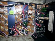
here are the connections on the back plane. I think you may have a couple labeled wrong.
Attachments

Michael F
Journeyman
Michael F
Journeyman
. I think you may have a couple labeled wrong.
I double checked everything and it`s good. Only the B- was labeled as un-fused but that has been since corrected.
Michael F
Journeyman
New control board installed (very nice btw). Backplane populated and all is good there, 0vdc offset both channels.
Left channel bias rock solid at 350mv however, I cant get more than .050v on the right channel board regardless of trimpot position.
Bias transistors were tested prior to being terminated on the new board.
Bias transistors were tested in-circuit and measure identically.
HELP!
Left channel bias rock solid at 350mv however, I cant get more than .050v on the right channel board regardless of trimpot position.
Bias transistors were tested prior to being terminated on the new board.
Bias transistors were tested in-circuit and measure identically.
HELP!
Michael F
Journeyman
Problem solved:
I forgot to replace the 1 amp rail fuses following the control board and transistor installation and start up .... Those tests were conducted with the DBT and variac in line. When bypassed, the initial rush current must have popped the right channel B+ fuse.
Bias steady on both channels, DC offset immeasurable but the nice surprise is the power output, 421 wpc @ 8r (single channel driven)
Dare I try a 4 ohm load? Will the 5 amp rail fuses be up to the task I wonder.
I forgot to replace the 1 amp rail fuses following the control board and transistor installation and start up
.... Those tests were conducted with the DBT and variac in line. When bypassed, the initial rush current must have popped the right channel B+ fuse.Bias steady on both channels, DC offset immeasurable but the nice surprise is the power output, 421 wpc @ 8r (single channel driven)
Dare I try a 4 ohm load? Will the 5 amp rail fuses be up to the task I wonder.
Glad your unwell turned into well...
Before you wrap it up totally Mike, you should ditch those CP-5 wirewounds in the Zoebel network and move to metal oxide to reduce the inductance. Inductance is self defeating in a Zoebel network.
- Joined
- Jan 14, 2011
- Messages
- 75,893
- Location
- Gillette, Wyo.
- Tagline
- Halfbiass...Electron Herder and Backass Woof
Problem solved:
I forgot to replace the 1 amp rail fuses following the control board and transistor installation and start up
Bias steady on both channels, DC offset immeasurable but the nice surprise is the power output, 421 wpc @ 8r (single channel driven)
Dare I try a 4 ohm load? Will the 5 amp rail fuses be up to the task I wonder.
No. The 5 amp rail fuses will blow at around 600 watts per channel at 4 ohms..
Michael F
Journeyman
Will it be able to do 600wpc into 4 ohms?No. The 5 amp rail fuses will blow at around 600 watts per channel at 4 ohms..
- Joined
- Jan 14, 2011
- Messages
- 75,893
- Location
- Gillette, Wyo.
- Tagline
- Halfbiass...Electron Herder and Backass Woof
Theoretically 770.
Michael F
Journeyman
OMG. What kind of rail fuses would support that kind of power,8 amps?Theoretically 770.
- Joined
- Jan 14, 2011
- Messages
- 75,893
- Location
- Gillette, Wyo.
- Tagline
- Halfbiass...Electron Herder and Backass Woof
Yep. And then you risk components when the high frequencies hit. 20 k at 770 watts at 4 ohms ain't happening..