grapplesaw
Veteran and General Yakker
LF 351??
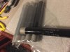
Lf 356 in this unit

LF 351??
OkThat's where I would start....
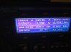
Yes offset was my bad. Bias is .350 no load.So the offset voltage problem is fixed......bias voltages are with no load correct?
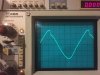
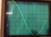
So far this think is operating correctly. I will have to get in touch with Ed and get more info on what was going haywire.bias will rise as the load increases....350mv is perfect with no input...
Ed and I talked about it today....wasn't it a runaway heat problem?? Could it be caused by a high frequency oscillation?
I started to pull it apart Lee. Going to Chan's the 2 bias transistors. Then we will pump it up.What's it do if ya lay the meat to it??
I will take out the 3403's and put in 5088's. I have been using #22 resently for leads. They are all more easy to place inbetween other cables that #20 gauge wire. I do not think they pass much current so unless some corrects me I will carry on with #22 leads3403"s or 5088's?