Mark embarks on the path of complete WOPLness

laatsch55

Administrator,
Staff member
Joined
Jan 14, 2011
Messages
75,030
Location
Gillette, Wyo.
Tagline
Halfbiass...Electron Herder and Backass Woof
#41
A few wiring questions:

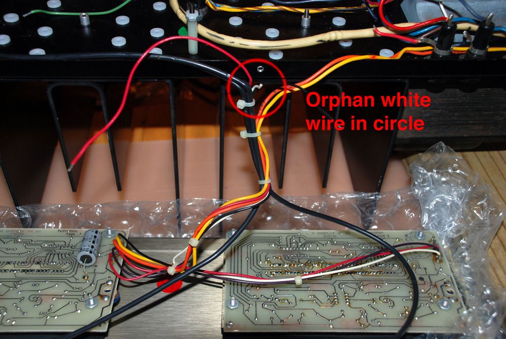
This is a 400 Series II- LED output meters. There's a red wire and a black wire coming from the meter driver boards- I deduce these are the meter inputs. These connect to OUT1 of their respective L/R backplane boards. There is also a white wire- assumption sez that this connects to the stud ground- correct?

The WA DC board uses an AC connection from a stud on the rectifier- route it above or below the backplane boards? DC connection will be via FUSED_B+_OUT on the R backplane, ground goes to the stud ground in the center of the L backplane.

Speaker outputs (OUT2- yellow wires at the top of the boards) route atop the backplane boards- should I route the speaker grounds coming from the copper strap above or below the backplanes? I know there's an issue here regarding inductance from AC wire proximity (the thermal switch) affecting noise in the amp.

Just wanted to clarify before I burned the house down...

The DC protect AC line should be routed on top. Ground from the DC protect goes to bus bar. The speaker positives should go straight to the Protect board from where they are. The speaker grounds should go down around the bottom.
 

laatsch55

Administrator,
Staff member
Joined
Jan 14, 2011
Messages
75,030
Location
Gillette, Wyo.
Tagline
Halfbiass...Electron Herder and Backass Woof
#44
The orange and red look like the meter signals. I believe the short white is the ground. I'd meter the ground on the meter board and see if you have continuity on the white wire...
 

Gepetto

Administrator
Staff member
Joined
May 15, 2011
Messages
14,098
Location
Sterling, MA
Tagline
Old 'Arn Enthusiast
#45
The red black and white wires are the right ground and left wires, same as the analog meters. Plus the AC input which gets rectified on the meter boards.
 

MarkWComer

Veteran and General Yakker
Joined
Nov 1, 2014
Messages
3,520
Location
Gaston, SC
Tagline
Victim of the record bug since age five
#46
The red black and white wires are the right ground and left wires, same as the analog meters. Plus the AC input which gets rectified on the meter boards.
Every other white wire was ground- same holds true here, then? I have no idea how the analog meters are wired- this is a Series II.
Clarify, I don't understand: "red black and white wires are the right ground and left wires" describes three colored wires, but only two functions: "...right ground, and left..." Shouldn't both have the same ground? (where's the left ground?).

AND: This ground connects to the stud ground or the strap ground?

The orange and red look like the meter signals. I believe the short white is the ground. I'd meter the ground on the meter board and see if you have continuity on the white wire...
Orange and red originate from the transformer. This is AC input. I wasn't concerned about those- I'm leaving them alone.
Looking for the trace on the circuit board that says, "this is the ground." How the hell do I find the meter board ground?
I have a schematic of the PL37 board, doesn't tell me much. Pin 1 of both IC Z302 and Z303 connect to ground...
 
Last edited:

MarkWComer

Veteran and General Yakker
Joined
Nov 1, 2014
Messages
3,520
Location
Gaston, SC
Tagline
Victim of the record bug since age five
#47
I believe the short white is the ground. I'd meter the ground on the meter board and see if you have continuity on the white wire...
Pin 1 of IC Z302 and IC Z303 both confirm continuity to the solder point of the white wire, tested the IC pins on both L/R meter boards, white wire confirmed as ground.

So.... Whatzit hookup to? The stud ground or the strap ground?
 

Gepetto

Administrator
Staff member
Joined
May 15, 2011
Messages
14,098
Location
Sterling, MA
Tagline
Old 'Arn Enthusiast
#50
Every other white wire was ground- same holds true here, then? I have no idea how the analog meters are wired- this is a Series II.
Clarify, I don't understand: "red black and white wires are the right ground and left wires" describes three colored wires, but only two functions: "...right ground, and left..." Shouldn't both have the same ground? (where's the left ground?).

AND: This ground connects to the stud ground or the strap ground?


Orange and red originate from the transformer. This is AC input. I wasn't concerned about those- I'm leaving them alone.
Looking for the trace on the circuit board that says, "this is the ground." How the hell do I find the meter board ground?
I have a schematic of the PL37 board, doesn't tell me much. Pin 1 of both IC Z302 and Z303 connect to ground...
Right
Ground
Left

both meter channels share the same ground Mark.
 

grapplesaw

Veteran and General Yakker
Joined
Aug 13, 2014
Messages
2,782
Location
Vancouver
Tagline
---
#51
Top to bottom left hand board
black is ground - connect at star ground between power caps
yellow power in From transformer ( Low voltage circuit wire 1/2 amp fuse on terminal block above power caps on left frame side)
orange power in from transformer ( low voltage circuit in transformer)
red power supply to right hand board
black power supply to right hand board ( ground?)
bottom red- signal in left Channel

right hand board
red and black - power supply
white - signal in
 
Last edited:

MarkWComer

Veteran and General Yakker
Joined
Nov 1, 2014
Messages
3,520
Location
Gaston, SC
Tagline
Victim of the record bug since age five
#52
OK, so squared away on everything as far as the wiring goes, still waiting for stuff from Mouser- which brings up a point. Reaching a level of frustration, not with the build and not with any confusion of what to do, but with availability of stuff in this state. There are no electronic supply houses! Looking for the stupid little crimp ferrules to extend the wires to the thermal cutoff, looking for shrink tubing, looking for some hookup wire- there's NOTHING HERE! I can find everything to run an AC line or to wire a house, but nothing in the way of these little doodads that I need to get the job done. This place SUCKS! At least Radio Shack was some help- but the two in this area are now bare walls.

I found wire ties...

Hemming and hawing how to do the next video in a lucid manner...
 

laatsch55

Administrator,
Staff member
Joined
Jan 14, 2011
Messages
75,030
Location
Gillette, Wyo.
Tagline
Halfbiass...Electron Herder and Backass Woof
#53
I feel your frustration, at least in Gillette there must be some DIY'ers left as we have a RS that's pretty well stocked plus an independent called Chris Supply that carries meters, Pomona, etc and is a dealer for NTE.....
 

MarkWComer

Veteran and General Yakker
Joined
Nov 1, 2014
Messages
3,520
Location
Gaston, SC
Tagline
Victim of the record bug since age five
#54
Curiosities...

The way the wires were wrapped around the thermal cutoff made it difficult to desolder. How much heat can this cutoff withstand before burning out? Is it possible that I could have damaged it? Continuity shows good right now in "cold" state...

Same thing for the fuse holders- hell of a mess to desolder due to the way the wires were wrapped. They look OK, but I wonder about thermal damage to them. (Yeah- I'm probably obsessing unnecessarily here...)

Do bridge rectifiers also "burn out?" Should I think about replacing it now just for the sake of having a "fresh" and "known good" rectifier in place? I'll be attaching capacitors to the legs, again- real strange wire wraps and difficult desoldering on this component. I don't really need to desolder here as much as get a hole to put the cap leads through. (haven't touched it yet...)

Maybe I'm just trying to present a reasonable order to Mouser instead of a paltry order of crimp-connect ferrules, at least put in an order worth justifying the shipping charge.

Hats off to Becky, wherever she may be, for the impossible-to-desolder wiring job she did...
 
Last edited:

laatsch55

Administrator,
Staff member
Joined
Jan 14, 2011
Messages
75,030
Location
Gillette, Wyo.
Tagline
Halfbiass...Electron Herder and Backass Woof
#55
Becky built a few of those. Mark I cut the wires off before trying to desolder on the BR and thermoswitch, then cook things a bit and pull the wire out with some small needle nose , then clean up with the desolder tool.

The thermoswitch is very robust, except for sidepulls on the tabs, they'll break at the bend. BR's are also pretty tough. I have not cooked one into oblivion yet, but I let it cool down after a difficult solder. You don't need a hole for the 4 new bypass caps on the BR, I just wrap the leads, trim and solder. Most upgrades to WOPL's include a new 35 amp BR, but we have since gone to 50 amps.....


The fuseholders are just plain fuckin tough....good thing too.....
 

MarkWComer

Veteran and General Yakker
Joined
Nov 1, 2014
Messages
3,520
Location
Gaston, SC
Tagline
Victim of the record bug since age five
#56
Becky built a few of those. Mark I cut the wires off before trying to desolder on the BR and thermoswitch, then cook things a bit and pull the wire out with some small needle nose , then clean up with the desolder tool.
Pretty much what I'm doing... Good! I'm safe!
The thermoswitch is very robust, except for sidepulls on the tabs, they'll break at the bend. BR's are also pretty tough. I have not cooked one into oblivion yet, but I let it cool down after a difficult solder. You don't need a hole for the 4 new bypass caps on the BR, I just wrap the leads, trim and solder. Most upgrades to WOPL's include a new 35 amp BR, but we have since gone to 50 amps.....


The fuseholders are just plain fuckin tough....good thing too.....
I will desolder one of the bridge connections, manly because I'm not satisfied with the way I attached the AC connection to the WA protection board. I just wrapped 'n' soldered, and it looks damned sloppy. Did I ever mention that I'm a touch on the obsessive/compulsive side?

It's a pleasure to be in contact with people who know more than I do!
 

MarkWComer

Veteran and General Yakker
Joined
Nov 1, 2014
Messages
3,520
Location
Gaston, SC
Tagline
Victim of the record bug since age five
#58
That teflon coated wire that comes in the wiring kit- does this stuff have a special name?

I'm gonna have to find a length of this somewhere- my output grounds aren't long enough to reach the DC board with the way I have to reroute them around the backplane boards.
 

Gepetto

Administrator
Staff member
Joined
May 15, 2011
Messages
14,098
Location
Sterling, MA
Tagline
Old 'Arn Enthusiast
#59
That teflon coated wire that comes in the wiring kit- does this stuff have a special name?

I'm gonna have to find a length of this somewhere- my output grounds aren't long enough to reach the DC board with the way I have to reroute them around the backplane boards.
MIL Spec M22759/11

What do you need to finish it off Mark. I included extra lengths of the white to cover that run too.
 

MarkWComer

Veteran and General Yakker
Joined
Nov 1, 2014
Messages
3,520
Location
Gaston, SC
Tagline
Victim of the record bug since age five
#60
MIL Spec M22759/11

What do you need to finish it off Mark. I included extra lengths of the white to cover that run too.
I used part of it for the ground to the DC protection board- looks like I screwed up in the wire allocation...

I need to find another 20" of the 18g wire. Should be commonly available, right?
 
Top