- Joined
- Jan 14, 2011
- Messages
- 75,509
- Location
- Gillette, Wyo.
- Tagline
- Halfbiass...Electron Herder and Backass Woof
Youre doing good Nelson....keep pluggin away..

the 1k is not critical Nelson, anything near that will do fineNot sure where I got that idea, mind playin' tricks on me again, damn mad cow!! Okay, well I'm going to go through my old fashioned brown background, striped resistors and look for a 1K 2W and get the charge out of these babies!
Almost anything above 2 watts will do , at least 100 ohms, they get a little warm under 1K....oh....and be sure to take them off before you power up....ask me how I know...
the 1k is not critical Nelson, anything near that will do fine
") I'm guessing that the good news will be that there's a simple explanation for the lack of B+ voltage at the B+ test points-perhaps a fuse?!?
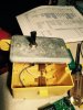
I'm guessing that the good news will be that there's a simple explanation for the lack of B+ voltage at the B+ test points-perhaps a fuse?!?I fashioned one after yours. However it is far from as good looking as your DennisThose damn big ass caps - they'll bite you if you're not careful. I've been bit a time or two so I built a simple circuit that has a three position switch - it is either open, has a 20 ohm or 50 ohm 10 watt resistor that is switched between two leads that I connect one to the capacitor plus side that I want to discharge and the other lead I connect to ground. I do this when the leads are open so no arc - just connect the two leads and throw the switch to one of the resistor positions to drain the cap. I also have two .080" jacks to plug a multimeter into so I can verify the voltage across the cap(s).
I've had test leads turn into plasma so I'm a bit shy about high voltage/high current. My last episode that turned metal into plasma was about 20 years ago but it's still fresh in my memory. I stayed from the test setup for the rest of that test day but was hard at it the following day.
Using a 4700 ohm, 3 watt resistor that I found in my stash I discharged the capacitors, added wires from the positive PS cap connection to the positive supply fuse tip and one from the negative PS cap connection to the negative supply fuse tip. While I was in there I decided to re-route the black B- and the green B+ wires from the top to the bottom of the chassis along with the two white negative output wires.
After making these changes I decided to power up again. This time I had voltage at both rail fuses and had good test readings on the B- but was not getting reading on the B+ test points. Thinking that I might not have had a good solder joint where I removed the B+ and re-soldered it so I removed the power, discharged the capacitors again and did some continuity testing. Everything seemed to pan out except there was no continuity from the any of the B+ attachment points to the B+ test points. I did however have continuity between the B- attachment points and the B- test points. I can't really come to any logical conclusion why this might be so but I'm new at this so there may be one. Later I'll go out and make sure the B+ rail fuse is intact, I didn't think to check that.
Anyway, the good news is that once again I got no odors, smoke or sparks when powering up!!
Ah......you are human.....or was that the fab house.....
That is because you discovered a previously undiscovered silkscreen label error on the board Nelson. Thank you for pointing that out to me. The Test Point labeled B+ (TP1) is really the Bias+ test point and the test point labeled BIAS+(TP2) is really B+ They are swapped
I will add this note to the release notes as an errata.
Thanks again.
Cannot blame the fab house, they faithfully produced the artwork I sent them.
Those damn big ass caps - they'll bite you if you're not careful. I've been bit a time or two so I built a simple circuit that has a three position switch - it is either open, has a 20 ohm or 50 ohm 10 watt resistor that is switched between two leads that I connect one to the capacitor plus side that I want to discharge and the other lead I connect to ground. I do this when the leads are open so no arc - just connect the two leads and throw the switch to one of the resistor positions to drain the cap. I also have two .080" jacks to plug a multimeter into so I can verify the voltage across the cap(s).
I've had test leads turn into plasma so I'm a bit shy about high voltage/high current. My last episode that turned metal into plasma was about 20 years ago but it's still fresh in my memory. I stayed from the test setup for the rest of that test day but was hard at it the following day.
")
Cannot blame the fab house, they faithfully produced the artwork I sent them.
I fashioned one after yours. However it is far from as good looking as your Dennis
two 47 ohm 20 watt can run one or both for near 100 ohm load,