Troubleshooting an humming WOPL : need help!

I use a 50w nobrando setable soldering station with silver solder (wich requires a lot of heat too). I actually had difficulties with keeping the threads in the hole without poping. With some expérience, the process is very straight forward.
As you may know, I own a little mechanical workshop. We are designing and building skids and small équipements for the process industry, especially for the pharma and brewing fields.
One of my daily question is to evaluate the human labor required by each of our project.
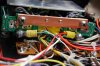
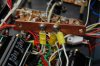
When I see what it takes to work on audio equipements I guess that the human labor has been the largest part of the price of audio equipements for long... For instance, I recently recaped a 1965 bang & olufsen integrated amp. A real bitch to work on, with very poor accessibility. It was hand made of course : I don't see how it could take less than 50hrs to build it. If such équipement had to be made today I could'nt imagine the price...

You should be using 63/37 solder, not silver solder.
 
Fellers, I have the 2000 boxed up and ready to go...it'll go out in the morning...
 
No need for that Florian, been meanin to get one into Joe's hands for awhile....
 
Thanks for the tip...

Kester SN63PB37 #50/245 It is the Kester 245 no clean flux. Even though it is no clean, it rinses easily with 90% isopropyl alcohol with no residue. Easier to clean up after than the Kester '44' classic rosin core.
 
Kester SN63PB37 #50/245 It is the Kester 245 no clean flux. Even though it is no clean, it rinses easily with 90% isopropyl alcohol with no residue. Easier to clean up after than the Kester '44' classic rosin core.
Thanks again Joe. The flux in my case is a real pain to clean.
I am in a business trip these days and I am visiting a guy who is using a lot of copper. Do you by chance know the dimensions of the caps bus bar? I d like to have a thicker one done.
Thanks in advance
 
Thanks again Joe. The flux in my case is a real pain to clean.
I am in a business trip these days and I am visiting a guy who is using a lot of copper. Do you by chance know the dimensions of the caps bus bar? I d like to have a thicker one done.
Thanks in advance

It's really your choice. I purchased a couple of sizes for the buss bar but I wanted one thick enough to screw a fastener into. The length should be similar to the buss bar you're replacing but I cut mine a bit longer, the width at least as wide as the existing bar but again the copper bar I used was a bit wider than the original and the thickness of the buss bar thick enough to get several threads tapped for the screws. Here are several photos with a measuring stick as a reference - it's not metric though.
 

Attachments

  • BABB.jpg
    BABB.jpg
    94.9 KB · Views: 30
  • BABB1.jpg
    BABB1.jpg
    96.8 KB · Views: 33
  • BABB2.jpg
    BABB2.jpg
    93.6 KB · Views: 33
It's really your choice. I purchased a couple of sizes for the buss bar but I wanted one thick enough to screw a fastener into. The length should be similar to the buss bar you're replacing but I cut mine a bit longer, the width at least as wide as the existing bar but again the copper bar I used was a bit wider than the original and the thickness of the buss bar thick enough to get several threads tapped for the screws. Here are several photos with a measuring stick as a reference - it's not metric though.

Thanks Nav!
 
Be careful on what diameter the threads are where the DC protect would go..you can only drill those holes out so much..
 
Hello there,

I am just coming back from a business trip so back to my backplanes assembly :)
I am putting in place the wires and I noticed that most of the wires I received in the kit are 18awg rather than 22. I suppose it's not a problem to replace the bigger ones by the thinners?

Thanks in advance,
 
Control board to driver board are 22 and 20. Bias tyranny is 24. Power wiring is 18.
 
Thanks Lee.
Just another quick question, if I understand well, the heatsinks for the bias transistors have to be salvaged from the cureent assembly, but I am not sure where these transistors have to be soldered as there are two positions : I suppose I've to solder it to the position reading 5088 as on the transistor...?
 

Attachments

Last edited:
Back
Top