
Hi there,
I'm back again after a few weeks rush at work...
I'd like to finish the works on my WOPL 400. I need to finish the installation of the backplanes and I also need to install the DC protection board Lee kindly sent me on.
As usual, I've a bunch of silly questions and I count on you guys to help me... :
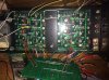
1- I soldered all the components on the backplanes board accordding the markings on the plastic pockets, I could'nt find a document describing the positioning of the jumpers on the boardi
2- I soldered the bias transistor on the sockets reading "5088" leaving the three sockets reading "3403" free. I assume this is correct.
I'm back again after a few weeks rush at work...
I'd like to finish the works on my WOPL 400. I need to finish the installation of the backplanes and I also need to install the DC protection board Lee kindly sent me on.
As usual, I've a bunch of silly questions and I count on you guys to help me... :
1- I soldered all the components on the backplanes board accordding the markings on the plastic pockets, I could'nt find a document describing the positioning of the jumpers on the boardi
2- I soldered the bias transistor on the sockets reading "5088" leaving the three sockets reading "3403" free. I assume this is correct.

")