OK then, back to the only
PROBLEM "Jesse" has. Every help is greatly appreciated!
When the power switch is turned OFF,
the Channel A (Left) VU Meter:
- Goes back and stands still at -20 (OFF) position;
- After 10 seconds (amp is OFF remember), pegs VERY rapidly to -1 position;
- From there, takes 12 seconds to slowly go back at -20 (OFF) position.
Some considerations:
- Channel B (Right) VU Meter is OK;
- Channel A VU Meter is responsive when ON, BUT is slightly "behind" Channel B by 0,5 units or so;
- Voltage check on bias and speaker binding posts: it is absolutely equal and steady when comparing L and R;
-
This was the only meter which pegged violently at turn-on BEFORE WOPLing/restoring the unit. This PL400 had the common problem of frying speakers via rail voltage, the reason why it was abandoned by previous owner;
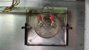
- Below a closeup of the meter type from
Honeywell. As per WO instructions and documentation, it is NOT the one type I could calibrate (if I understood right).
Some questions:
1) Is the thing gone for good? I really san't see how to operate here...
2)
As per pics above, this is the meter extremely close to the new power caps, which are way larger than the originals. Electromagnetism?
Aliens?
3) Would the White Oak LED Board somehow solve this?
Thanks in andvance for any help or considerations!
Carl
Carl182,
I think that with a bit of experimentation we can narrow down where the problem is being created, and at that point you can better decide if you want to pursue the actual fix. (If nothing else, you (and I) will get to learn a little more about the VU meter setup on the older PL amps.)
1) Alright, it that amp was mine, the first thing I would want to prove to myself is whether the VU meter is the
perpetrator of the visual anomaly
OR the
victim of the circuitry that's feeding it.
2) IF this was a mono amplifier, and there was ONLY 1 meter, then we would have to dive deep into the circuitry. But the hidden beauty of working on a stereo amp like yours is that we have
2 (hopefully) identical channels. This is good news, for it will help us to quickly determine if the VU meter is the victim or perpetrator. NOTE: If below we determine that the meter is good, then we have not 1 but possibly 2 victim scenarios. The 1st scenario is that the circuitry attached to the meter is causing the anomaly. The 2nd victim scenario is a geographic one -- that is, the proximity of the new power supply capacitors are somehow interfering with the meter? And furthermore, is it possible to have both victim scenarios in tandem, each contributing a share of the problem? A: Possible, but can't predict probability yet -- too little information.
3) Intermittent problems can be
the hardest to successfully troubleshoot/fix. As I used to teach Avionics troubleshooting to the young airmen, "You can't fix an intermittent problem until you can first break it at will." (!) I emphasized this to every student, because instead of just waiting passively for the problem to present itself, I instead needed them to reason through the fault, come up with ALL possible scenarios that could cause the fault, and then try to figure out how to stimulate the fault with the tools & test equipment at their disposal.
Q: Are you asking yourself why I would bring up the intermittent scenario? A: Because from your description, you have
already figured out how to stimulate the fault, and it happens every time -- that's a bonus! Assuming that you don't lose interest and/or are forced to push the fix to a lower priority, there's a very high probability that we can & will fix this!
****
Here we go. NOTE: For the purposes of this test, I am going to assume for now that both Left & Right audio channels are working identically. (That is, what the meters are monitoring is exactly the same. (I assume that the music output at both speakers are the same level, no distortion, etc.)
(Of course, standard safety procedures apply. Power down -> Unplug -> discharge the PS caps -> then proceed. (As you must have already been doing throughout your rebuild project...since you are still here. :0)
a) Disconnect the suspect (Left) meter from the circuit. Have a pair of alligator clip jumper wires on hand. (Safest approach) Now disconnect the GOOD meter from it's circuit. Now jumper the suspect (left) meter to the 'known-good' (right) circuitry. Make sure nothing is going to short out against the chassis and/or other unrelated circuits. (Accidental collateral damage is never fun. :0(
Power up, run a few seconds of music through it, and observe that the suspect meter is dancing as it should.
NOW, power it down & watch carefully. Q: Does the suspect meter
still misbehave? If NOT, then we get to declare that the suspect meter is a VICTIM of the drive circuitry it is normally connected to. NOTE: If it is working correctly now, this also proves that the nearby capacitors must not be affecting the meter's behavior. (!)
On the other hand, IF the suspect meter is still showing the same bad behavior after shutdown while connected to the 'known-good' circuit, then the meter is the perpetrator of the fault, and you have to decide if you want to pursue repair or replacement.
****
Given the symptoms, plus your observation about how the meters BOTH worked pretty close to the same while the amp was on/playing music, while the meter being bad is a possibility, it's a higher probability that a component was wounded by the failure in the left channel prior to you acquiring the amp. (I *think* that this is the correct schematic for your amp, but please verify first before following.)
IF THE METER WORKS PROPERLY IN THE GOOD (right) CIRCUIT BUT INCORRECTLY ON THE BAD (left) CIRCUIT, THEN WE NEED TO LOOK AT THIS:
So, please find the circle with the "VU" written inside. Notice the diode & resistor that the VU meter is connected to. I would want to find them physically and give them a close visual inspection. (Especially D17) Actually I would compare the VU meter circuitry on the Left channel and compare it closely to the right channel, and anything that doesn't match would warrant further investigation.
****
We could go on & on, meters & scopes, monitor how the DC rail voltage decays in 12 seconds, etc., any old electrolytic caps in the neighborhood, etc...but let's stop here for now & find out which of the 3 possible scenarios we are dealing with before going any deeper?
1) GOOD meter, victim of bad drive circuitry.
2) GOOD meter, GOOD drive circuitry, proximity effect of power supply caps.
3) BAD meter, otherwise good circuitry & physical meter location not an issue.
Take your time, enjoy the troubleshooting journey, and when you get a chance to post your findings we will pontificate further at that point. :0)
Good luck --
3D