WOPL 400 Down Under

Timmienator

Journeyman
Joined
May 24, 2021
Messages
61
Hi all
I am already a proud owner of a PL400 4 finner that I have modified slightly with your help and am back again.


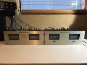
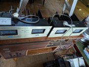
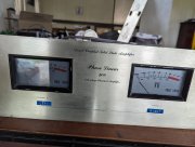
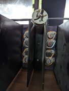
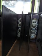
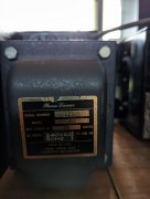
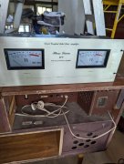
A couple of months ago I came across a PL400(8 finner) on fleabay, made some enquiries and found out there were 2 units for sale so I paid for both. All I know about them is I purchased them from a recording studio, 1 unit functions except for vu lights and the other has only 1 channel functioning. A family member should be delivering them in the next couple of days.
I received a message from Joe the other day that my parts were being shipped and am also awaiting an invoice from Don for his bits.
My initial plan was or is to full WOPL on the best original chassis/ faceplate and just restore the other to flip.
My question is

Do I spend some time getting the other 8 finner ready for sale before the WOPL road or save time and energy because I will then want 2 X WOPL400s?
And do I have to install parts upside down because I am here in Oz?

Was hoping I could post here my build really and probably ask some questions if ok?

Cheers
Timmie
 

Attachments

  • IMG_20220804_163904.jpg
    IMG_20220804_163904.jpg
    159.4 KB · Views: 31
welcome aboard...
these guys helped me restore a 4 fin, an 8 fin, and we converted another 4 fin to full wopl...along with a pl200 and pioneer sx1080...rest assured they will assist you...tons of talent and generosity here...just a heads up...pics...lots of pics...
good luck
 
Welcome, you are in the right place for your PL400 rebuilds. You should briefly listen to the amp with two working channels; it will never sound the same after the rebuilds, just better, so much better. Oh, you will want two WOPL 400s. This is a slippery slope...
 
Mlucitt that's what I'm worried about

Still waiting on delivery of the amps so am trying to do some proactive thinking now.

As I have limited knowledge/experience with electronics I was considering fixing the broken unit first to learn about fault finding and brush up my soldering skills before starting the WOPL build.
Also after reading some more of the literature Joe has emailed me it seems I need to purchase a Variac. The documentation states a Variac rated 1200Va is needed however I can only find one available here in Aus that is 500Va.
Will it do the job?
Does the fact we are 240v here change anything?
Also how does one bring up an amp when using 240v as opposed to 120v?

Sorry I am a novice with a huge thirst to learn

PS After the two 400s are done I will be tackling the pictured Pioneer tube receiver so want the Variac for that also.
 

Attachments

  • PXL_20210130_111223083.jpg
    PXL_20210130_111223083.jpg
    3 MB · Views: 19
Gene
Here's one I prepared earlier for my 4 finner. Agreed that it doesn't look nice but it works and works safely.
I am awaiting delivery on the latest 2 400s in the next few hours so be prepared for an onslaught of pics soon!
 

Attachments

  • PXL_20221005_015509128.jpg
    PXL_20221005_015509128.jpg
    2.3 MB · Views: 26
Gene
Here's one I prepared earlier for my 4 finner. Agreed that it doesn't look nice but it works and works safely.
I am awaiting delivery on the latest 2 400s in the next few hours so be prepared for an onslaught of pics soon!
it aint a beauty contedt!!!lolol
good enough ....
i am old .... make plenty of mistakes...bdt saved me more than once ..
they helped me restore a 4 fin...i did add fins later to help out the heat...an 8 fin...and i converted a burnt 4 fin to full wopl and added fins so all units have 8 fins...i also recapped a pl200 and an sx1080 pioneer...if you let them...they will guide you...tons of talent here...i bought a dsp and have a phase linear quad amp system...it is a slippery slope and addicting...
take care...
best wishes!!!
 
Just got them home.
Not in quite as good physical condition as the photos led me to believe.(I should know better by now)
Rare as hens teeth here in Oz .....
Am in way too deep now to back out
Prepare yourselves for the incoming pics and questions!
 

Attachments

  • PXL_20221005_034946039.jpg
    PXL_20221005_034946039.jpg
    2.5 MB · Views: 22
The unit apparently outputting DC in left channel PXL_20221005_035824183.jpg
 

Attachments

  • PXL_20221005_035808380.jpg
    PXL_20221005_035808380.jpg
    2.7 MB · Views: 21
  • PXL_20221005_035833838.jpg
    PXL_20221005_035833838.jpg
    2.2 MB · Views: 22
  • PXL_20221005_035838154.jpg
    PXL_20221005_035838154.jpg
    2.2 MB · Views: 20
The working unit apparently!

Now for a quick clean then bring them up for testing
 

Attachments

  • PXL_20221005_040506110.jpg
    PXL_20221005_040506110.jpg
    1.8 MB · Views: 13
  • PXL_20221005_040450089.jpg
    PXL_20221005_040450089.jpg
    2.6 MB · Views: 16
  • PXL_20221005_040521799.jpg
    PXL_20221005_040521799.jpg
    1.6 MB · Views: 14
  • PXL_20221005_040511895.jpg
    PXL_20221005_040511895.jpg
    1.5 MB · Views: 14
The working unit apparently!

Now for a quick clean then bring them up for testing
mismatched outputs....you have delcos mixed with fairchilds....you are not supposed to do that within one channel...xpl go with xpl and f pl goes with f pl...within a channel...
i did not know that motorola chip mj10524 was a legit replacement for the 909...i knew the 2sd555 was ...its listed in the service manual...
live and learn...
 
Gene
I totally agree with you re the outputs however I have only just got the units so powered them up to get a benchmark.
The unit with the faulty channel is throwing 65v DC at the left output. Where should I start looking for the source of this?
 
if the rail fuse on left channel is blown ..remove all outputs marking their position and test transistor by transistor....be careful...this stuff is almost 50 years old...do you know how to do that??
if you start removing outputs...wait about 5 minutes before you touch the transistors with a screwdriver...the case of the transistor is the collector...if you short to a fin...it could spark or shock you if you act as ground...ask me how i know...
 
Gene
Thanks for that reminder.
Here's a couple of things I wasn't expecting.
1. Balanced inputs on both units..... Dunno how I can make that look good
2. My 4 finner didn't have this PCB anywhere so I guess I'm asking is it a Oz add on?
 

Attachments

  • PXL_20221005_052234800.jpg
    PXL_20221005_052234800.jpg
    2.2 MB · Views: 33
  • PXL_20221005_052111124.jpg
    PXL_20221005_052111124.jpg
    1.7 MB · Views: 32
they could be just using the balanced jacks...
i had to change all input rca jacks for gold plated ones...watts used to send replacements with his dcprotect board because of so many bad ones...now they are optional..do you have the dc protect??
if not...and whoever had the shorted outputs in left channel now has a left channel speaker that dont work any more...even with dcprotect i still used disposible speakers for testing...i did smoke one set of those...troubleshooting....
 
the
Gene
I totally agree with you re the outputs however I have only just got the units so powered them up to get a benchmark.
The unit with the faulty channel is throwing 65v DC at the left output. Where should I start looking for the source of this?
dc is actually higher...the dbtester is holding it down...if you switch to line voltage it would approach 80v...
 
Back
Top