- Joined
- Jan 14, 2011
- Messages
- 75,684
- Location
- Gillette, Wyo.
- Tagline
- Halfbiass...Electron Herder and Backass Woof
If distortion was audible, run a sweep from 20hz to 20khz..

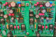
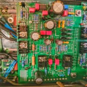
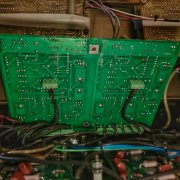
Just for reference guys, Zach has RevD PL400 backplanes installed and a RevG1 control board installed based on his order history. This may head off some additional questions you may be wondering about. I am assuming that Zach installed what he ordered.
Oh yeah, that makes sense. Why pick one frequency when I can have them all.If distortion was audible, run a sweep from 20hz to 20khz..
Damn Sniff, did someone $hit in your raisin bran this morning.
The ability to solder and the need to test a transistor are not mutually exclusive. Hell, they're barely related. As I mentioned in my post, electronics as a hobby have always take a back seat to other interests. See below for an example of a hobby that I've focused on instead. I designed and built the entire thing by hand View attachment 64915
I want this project finished more than anyone here. The easy path would be to have someone else just tell me what's wrong. In case you missed it in the original post, I put this kit together to further my knowledge. Confronting and working through this problem will do more for my advancement than anything else.
You're a native English speaker and have never heard of a Tilde?????? It looks like this ~ and it means "approximately". Glad you had the opportunity to learn something from me, I just wish I could say the same.
Oh yeah, that makes sense. Why pick one frequency when I can have them all.
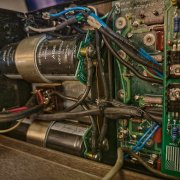
I was taking the scope for a test drive along with the amp a couple weeks ago. I had 8Ω resistors across the outputs along with the scope. At a very specific point the sine wave "grew spikes". I thought it was interesting but unimportant in the moment. Last night I was watching a video of a scope measuring a transformer that was overloaded (?) or otherwise failing and it showed the EXACT same signature.
If I do find that I've ruint this transformer, what are my replacement options? I am not concerned with form factor in the least. Do you know if there are toroidal transformers available that meet the specifications for this amp? If so, I'd probably go for a pair to get true separation.
I've read that the 700 has a higher rail voltage than the 400. If I am able to find replacements, can I increase the voltage for additional headroom? What are the trade-offs? What is the upper limit?
I appreciate your time and input. Really.
It should measure ~+85VDC and ~-85VDC then......
I asked for help in learning how to troubleshoot a problem. I'm not interested in being spoonfed the answers. You and I are not the same.
I'm not interested in being spoonfed the answers. You and I are not the same.
Hi Zach
What the guys are trying to tell you is that many debugs have occurred through the benefit of this forum and the folks here that are willing to help with problems. No one here can guess their way to your success.
EVERY SUCCESS was because pictures were shared which usually led to a finding and a subsequent solution. Like you shared a photo of your motor with us, the generous guys here need something to go on.
They will get coated with a true ceramic by SwainTech. If that's not enough, I'll wrap them as well.I like your piping right up until it enters the collector for the turbine. You have the blow-off valves there too but otherwise it looks like a decent flow path.
My other concern is the radiant heat from those pipes hugging the block. Oil temps from that, and (I assume) the turbo oil, will drive temps to the sky. The oil cooler will be larger than the intercooler…
Looks awesome!


The easy path would be to have someone else just tell me what's wrong
SpoonFed?? That don't SOUND like what your asking for.
Yer right, we're nothing alike
I'm shocked that the admins on this site allow this type of behavior. I would expect this kind of thing on a site with a teenage demographic but not on a site composed of accomplished adults.
You lack tact and class. Your sophomoric, adolescent, and unprovoked criticisms do nothing to advance the discussion.
You bring the collective IQ and EQ down significantly. Your behavior reflects poorly on this entire group. It's unfortunate.
I've spent years eliminating this kind of behavior from my life. I have zero tolerance for this level of immaturity. I certain that you lack the minerals to speak like this when face to face.
I came here for help with a basic problem in a hobby that is STRICTLY for enjoyment and a way to unwind.
I expected an enjoyable exchange with fellow enthusiasts. Instead I've found my self irritated with your nonsense. You've sucked the fun out of this experience for no reason other than to stroke your fragile ego.
I appreciate the help and advice from the other members here but I'd rather figure this problem out on my own than suffer through any more of your vitriol.
I'm closing and deleting my account.