White Oak Audio Design - Model ONE 1000 Watt Stereo Amplifier

wattsabundant

Chief Journeyman
Joined
Apr 26, 2011
Messages
863
Location
Central Ohio
Do we really give a rats ass about the knob being original-like to a PL?

Also, I need some measurements when you are far enough along so I can get a cabbage case built. No way should those puppies be shipped in anything less. It will belong to the forum to be used by anybody shipping a Model 1....hell;, I'll get two built if we need to...
Cabbage Cases is about 20 minutes away form me. I can inspect/approve the prototype before shipping as needed.
 

mitscm

New Around These Parts
Joined
Dec 3, 2023
Messages
7
Thank You Joe, for sharing your passion with all of us. This is exciting !!!!!
We have a unique group of people here on the forum, and the creativity, engineering, and dedication of us all is exemplified in the continuous improvements you strive for.....
"Always working on making it better... "
I cannot say enough for the assistance and passion from Joe and Mark to help me restore my Blaze400s2 to a PhaseLinear! This old girl (Built by Pat) was a blaze400 at the StonePoney in Asbury Park NJ in 82’ when I (swapped it for a Dynaco400 on a Saturday night) first fixed it the left outputs, 40yrs later - now powered by White Oak - and good for the next 40! Thank you Joe and Mark! Merry Christmas.
 

Attachments

mlucitt

Veteran and General Yakker
Joined
Jun 24, 2011
Messages
3,397
Location
Jacksonville, FL
Lee, the dimensions for the WOA Model ONE are the same as the PL700 in height (7 1/8") and width (19" Rack). The difference is the depth - 21".
 

mlucitt

Veteran and General Yakker
Joined
Jun 24, 2011
Messages
3,397
Location
Jacksonville, FL
I have been remiss on not posting my progress of the WOA Model ONE assembly. There have been some delays caused by identifying better parts, changes to the documentation and the Wire Run List, but I am making progress.
The picture below shows the IEC Power Inlet. It looks like the Shield Wire is perilously close to the Fuse Holder, it is not. It is wrapped around the Ground Wire. The Ground Wire is connected to a pressed-in stud in the chassis. I chose a shielded Power Wire, but the run is only about 6".

01 AC Wiring.jpg

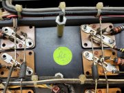
This picture shows the same Backplane Boards as used in the PL700 with the exception of Pin Headers instead of Phoenix connectors.
02 Backplane Detail for Model ONE.jpg

Standard PL700 Backplane Hardware is also used. You can also see the Balanced Input XLR connector is pre-wired. Due to the close proximity of the Transformer Cover to the back wall of the Chassis, all connectors should be pre-wired before installation.
03 Standard Backplane Hardware.jpg

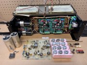
This was my mock-up "fit test" of the Backplane Boards and the Output Relay Board. Note that the Thermostatic Switches have large Faston terminals. This means the Backplane Boards are installed first, then the Thermostatic Switches go in afterwards.
04 Output Relay and Backplane Boards Test Fit.jpg

When installing the Transformer, I tightened down the Holding Bolt finger tight, then added a turn with a wrench to compress the rubber pads lightly. Install the smaller 25VA Toroid on the outside of the Transformer Cover, then install the Transformer Cover onto the Chassis. The center-back washers and nut are real fun to install, ask me how I know...
06 Oooops Now I Am Screwed.jpg

The amplifier is now ready for the Backplane Boards. The Transformers and Transformer Cover have to be installed before the Backplane Boards because. Just because.
07 Amp Ready For Backplane.jpg

The Backplane Boards are simply resting in place so I can verify the length of each wire. The Red and Black Wires of the Dual Primary 1.5KVA Transformer come out of the rear and the Secondary Windings come out of the front of the Transformer Cover. The Yellow and Brown Secondary Wires will be trimmed and pushed back into the Transformer Cover because they are not used, but they may be used in the future.
05 1.5KVA Toroid and Cover Installed and Backplane Boards Wired.jpg

I used a couple of 2x4 blocks to tilt the amplifier on the cart to install the Backplane Boards. This keeps the Nylon spacers from falling out.
08 Tilt Amp to Install Backplanes.jpg

The WOA 1000C (Classic) Amplifier Boards are installed next. One of the screws is a little tricky to install. Note how the Backplane Board Pin Headers fit into the Phoenix connectors perfectly.
09 Tight Screw Clearance.jpg

The threads in the pressed-in nuts are so precise that the screws need to be carefully aligned to start the threads. Much better than sheet metal screws...
10 Long Screwdriver Needed.jpg
 

Hexis22

Chief Journeyman
Joined
Dec 28, 2022
Messages
554
Location
Wisconsin
Very interesting.

Looking forward to see how the caps are wired in and how Grounds are connected.

Like the barrier terminal strips, lack of wiring between the backplane and control boards, and use of improved speaker output terminals.
 

Gepetto

Administrator
Staff member
Joined
May 15, 2011
Messages
13,592
Location
Sterling, MA
Tagline
Old 'Arn Enthusiast
Very interesting.

Looking forward to see how the caps are wired in and how Grounds are connected.

Like the barrier terminal strips, lack of wiring between the backplane and control boards, and use of improved speaker output terminals.
The slide show link shows some of the barrier strip wiring details near the end. It shows how the caps are wired in and the grounds are connected.

Model ONE Step by Step slide show IMG_6939.JPG
 
Last edited:

Gepetto

Administrator
Staff member
Joined
May 15, 2011
Messages
13,592
Location
Sterling, MA
Tagline
Old 'Arn Enthusiast
Thanks Joe.

I was thinking more from a high frequency noise perspective.

Given the distance between the RCA inputs, it's difficult to obtain a high frequency low impedance connection.
You don't need to, it is a ground loop shunt. That is its purpose...
 
Top