Hello everyone hope everyone is well ,, my question is I bought a speaker protection board for my 700 b from watts abundant , just waiting to get it in the mail Anyways , my question is how much dc offset will it take for these relays to kick in and shutt off the speakers my dc off set voltage was if I can recall,, left output was 0.08mvthe right out put was a little higher 0.024 mv , they say any readings under 50mv is acceptable , I’m just curious in much dc volts it would take to activate those 2 relays , thanks oeter

Watts speaker relay
- Thread starter v65magna
- Start date
- Joined
- Jan 14, 2011
- Messages
- 74,494
- Location
- Gillette, Wyo.
- Tagline
- Halfbiass...Electron Herder and Backass Woof
- Joined
- Jan 14, 2011
- Messages
- 74,494
- Location
- Gillette, Wyo.
- Tagline
- Halfbiass...Electron Herder and Backass Woof
- Joined
- Jan 14, 2011
- Messages
- 74,494
- Location
- Gillette, Wyo.
- Tagline
- Halfbiass...Electron Herder and Backass Woof
Hello everyone hope everyone is well ,, my question is I bought a speaker protection board for my 700 b from watts abundant , just waiting to get it in the mail Anyways , my question is how much dc offset will it take for these relays to kick in and shut off the speakers my dc off set voltage was if I can recall,, left output was 0.08mvthe right out put was a little higher 0.024 mv , they say any readings under 50mv is acceptable , I’m just curious in much dc volts it would take to activate those 2 relays , thanks oeter
Attachments
-
352.9 KB Views: 39
-
24.3 KB Views: 31
George P bought a 400 and 700 board back in February. He also asked for a couple of the chips used in the 400 board and I threw them in N.C. I think I sent him the 400 schematic. I figured he was doing some research.
When I developed the 400 board about 15 years ago I didn't intend to do the 700. Compared to the 400, there weren't that many 700's out there. Gibsonian hit me up a couple times for a 700 board as he had a bunch of 700B's. I didn't feel comfortable trying to take the 400 design from 80 volts DC to the 700's 100 volts DC for safety reasons. 100 VDC is no laughing matter.
My 700 board is very different than my 400 board. I designed the 400 from scratch. The 700 is the exact same circuit used in the 200, 300, 500, and the Carver C500 with one exception. I use a "form C" relay in both boards.
Relay contacts come in 3 common configurations. The "normal" state is de-energized or shelf state. A form "A" contact is normally open (ANO). it is closed when the amp is turned on. A form "B" contact is normally closed (BNC). It's contact is open when the amp is on. A form "C" contact has a common terminal and one ANO and one BNC. Phase Linear used a form A (normally open).
I use a Form C contact on each channel. Here's why. The common failure mode of an amp is to dump 80-100 VDC into the speaker. A circuit detects DC and tells the relay to open. When the relay tries to open, there is high current flowing through the contacts and the contacts arc. With DC, the arcing welds the contacts. The form C relay uses the normally closed contact to short out (crowbar) the speaker . The relay could fail but that's ok if it protects the speaker.
So why didn't P/L use form C relays? They probably cost more. Look at any amp or receiver and you find a form A contact. When the amp fails the contacts weld and the speaker is still damaged. I have a relay on my bench from a Marantz 140 with welded contacts.
George is right about the relatively high DC trip level of my 700 board. Ed pointed that out in a post here at least 5 years ago. Despite that, I opted to go with the P/L design for the 700 board because I liked the discrete circuit for the higher voltage and P/L and Carver both used it. They had to have a good reason and I don't think it was purely lowest cost. I didn't second guess it.
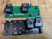
Early on Perry bought some of my blank 700 boards for his amps. Later he designed his version of my 700 board. We know he's built a lot of amps and I assume he puts one in each amp he builds. It's the black one in the photo next to my green 700 board. Same relays, same circuit. He opted to crowbar the output of the amp rather than the speaker. That was a head scratcher. Took me a while to figure that out.
George's 700 version looks like he laid it out very similar to my 400 board. The right and left amp input Phoenix connectors has an unused pin in the middle. I was concerned that people would not twist the stranded wire from the amp good enough resulting in the output being shorted. The extra spacing makes it almost impossible make a mistake.
It looks like George uses surface mount resistors which allows him to get the extra power supply circuits on a small board.
When I developed the 400 board about 15 years ago I didn't intend to do the 700. Compared to the 400, there weren't that many 700's out there. Gibsonian hit me up a couple times for a 700 board as he had a bunch of 700B's. I didn't feel comfortable trying to take the 400 design from 80 volts DC to the 700's 100 volts DC for safety reasons. 100 VDC is no laughing matter.
My 700 board is very different than my 400 board. I designed the 400 from scratch. The 700 is the exact same circuit used in the 200, 300, 500, and the Carver C500 with one exception. I use a "form C" relay in both boards.
Relay contacts come in 3 common configurations. The "normal" state is de-energized or shelf state. A form "A" contact is normally open (ANO). it is closed when the amp is turned on. A form "B" contact is normally closed (BNC). It's contact is open when the amp is on. A form "C" contact has a common terminal and one ANO and one BNC. Phase Linear used a form A (normally open).
I use a Form C contact on each channel. Here's why. The common failure mode of an amp is to dump 80-100 VDC into the speaker. A circuit detects DC and tells the relay to open. When the relay tries to open, there is high current flowing through the contacts and the contacts arc. With DC, the arcing welds the contacts. The form C relay uses the normally closed contact to short out (crowbar) the speaker . The relay could fail but that's ok if it protects the speaker.
So why didn't P/L use form C relays? They probably cost more. Look at any amp or receiver and you find a form A contact. When the amp fails the contacts weld and the speaker is still damaged. I have a relay on my bench from a Marantz 140 with welded contacts.
George is right about the relatively high DC trip level of my 700 board. Ed pointed that out in a post here at least 5 years ago. Despite that, I opted to go with the P/L design for the 700 board because I liked the discrete circuit for the higher voltage and P/L and Carver both used it. They had to have a good reason and I don't think it was purely lowest cost. I didn't second guess it.
Early on Perry bought some of my blank 700 boards for his amps. Later he designed his version of my 700 board. We know he's built a lot of amps and I assume he puts one in each amp he builds. It's the black one in the photo next to my green 700 board. Same relays, same circuit. He opted to crowbar the output of the amp rather than the speaker. That was a head scratcher. Took me a while to figure that out.
George's 700 version looks like he laid it out very similar to my 400 board. The right and left amp input Phoenix connectors has an unused pin in the middle. I was concerned that people would not twist the stranded wire from the amp good enough resulting in the output being shorted. The extra spacing makes it almost impossible make a mistake.
It looks like George uses surface mount resistors which allows him to get the extra power supply circuits on a small board.
George P bought a 400 and 700 board back in February. He also asked for a couple of the chips used in the 400 board and I threw them in N.C. I think I sent him the 400 schematic. I figured he was doing some research.
When I developed the 400 board about 15 years ago I didn't intend to do the 700. Compared to the 400, there weren't that many 700's out there. Gibsonian hit me up a couple times for a 700 board as he had a bunch of 700B's. I didn't feel comfortable trying to take the 400 design from 80 volts DC to the 700's 100 volts DC for safety reasons. 100 VDC is no laughing matter.
My 700 board is very different than my 400 board. I designed the 400 from scratch. The 700 is the exact same circuit used in the 200, 300, 500, and the Carver C500 with one exception. I use a "form C" relay in both boards.
Relay contacts come in 3 common configurations. The "normal" state is de-energized or shelf state. A form "A" contact is normally open (ANO). it is closed when the amp is turned on. A form "B" contact is normally closed (BNC). It's contact is open when the amp is on. A form "C" contact has a common terminal and one ANO and one BNC. Phase Linear used a form A (normally open).
I use a Form C contact on each channel. Here's why. The common failure mode of an amp is to dump 80-100 VDC into the speaker. A circuit detects DC and tells the relay to open. When the relay tries to open, there is high current flowing through the contacts and the contacts arc. With DC, the arcing welds the contacts. The form C relay uses the normally closed contact to short out (crowbar) the speaker . The relay could fail but that's ok if it protects the speaker.
So why didn't P/L use form C relays? They probably cost more. Look at any amp or receiver and you find a form A contact. When the amp fails the contacts weld and the speaker is still damaged. I have a relay on my bench from a Marantz 140 with welded contacts.
George is right about the relatively high DC trip level of my 700 board. Ed pointed that out in a post here at least 5 years ago. Despite that, I opted to go with the P/L design for the 700 board because I liked the discrete circuit for the higher voltage and P/L and Carver both used it. They had to have a good reason and I don't think it was purely lowest cost. I didn't second guess it.
Early on Perry bought some of my blank 700 boards for his amps. Later he designed his version of my 700 board. We know he's built a lot of amps and I assume he puts one in each amp he builds. It's the black one in the photo next to my green 700 board. Same relays, same circuit. He opted to crowbar the output of the amp rather than the speaker. That was a head scratcher. Took me a while to figure that out.
George's 700 version looks like he laid it out very similar to my 400 board. The right and left amp input Phoenix connectors has an unused pin in the middle. I was concerned that people would not twist the stranded wire from the amp good enough resulting in the output being shorted. The extra spacing makes it almost impossible make a mistake.
It looks like George uses surface mount resistors which allows him to get the extra power supply circuits on a small board.
View attachment 74957
Using your boards in all 3 of my 700b's.
Further clarification:
All DC protection circuits, every damn one of them, is a compromise. To reproduce sound a speaker pushes air back and forth. The amplifier drives the speaker. The rate that the speaker moves, how many times per second, is the frequency. Bass frequencies are relatively slow. 50 Hertz means the woofer moves back and forth 50 times per second.
The amplifier is fed 60 Hertz AC from the wall and converts it to DC voltage. The music tells the amplifier to switch the DC off and on which converts the DC to AC. As the DC voltage increases, the amplifier output power increases. 80 volts DC (400's) = about 200 watts of output power. 100VDC (700's) = about 350 watts.
The most common failure in an amplifier is shorted (welded) output transistors. The outputs then stop switching and send full DC to the speaker. The speaker moves as far as it can in one direction. If it's + DC the speaker moves forward. If it's negative DC the speaker retracts inward. If it doesn't keep constantly moving back and forth, or return to it's normal position, the speaker burns up. Specifically, the woofer burns up. The speaker system has a crossover with capacitors for the midrange and tweeter which blocks DC. Rarely does the woofer have coupling capacitors so it sees the full DC voltage.
The compromise in the DC detection circuit is the fact that the circuit has differentiate the difference between DC and very low bass frequencies. 10 Hertz is very close to DC. With some calculations the designer decides what frequency is normal low bass. Anything below that is DC. So if the decision is 10 Hertz any thing between DC (zero Hertz) and 10 Hertz trips the relay. 10 Hertz = 0.10 seconds (1/10).
Every cycle the detector looks at the voltage from the amplifier and measures it. It measures the positive and negative voltage. Once the voltage level goes above a threshold, say one volt, the detector starts a time delay. When the amplifier output voltage returns to zero volts (at the end of the cycle) the timer resets to zero and waits for the next cycle to go above the threshold. The whole timing cycle starts over again. If there is DC on the amplifier output (or very low bass) the detector turns off the relay.
What does this all mean? It's a compromise. You can detect a very low threshold of DC voltage. To avoid the relay from turning off at low bass you have to add a long time delay. If you're willing to accept a higher threshold voltage for detection, you can have a shorter time delay. It's not a perfect world. It's complicated by the fact that relays are mechanical and move at their own pace regardless of what their coil voltage is. Larger relays have more mass and move slower.
The integrated circuit that George and I used is only rated for about 60 VDC. I learned that the hard way which is a topic for another day. The nice thing about it is flexibility to make all of your calculations because there are hundreds of transistors with lots of timing circuits packed into one chip. To use it in a 700 you have to overcome it's voltage limitations. Things get more complicated.
The discreet 3 transistor circuit that Phase Linear, and later Bob Carver used, and I copied, accepts a higher level threshold, as George and Ed have pointed out. It still triggers as fast as you can with a simple, relatively high voltage circuit and avoids nuisance trips.
The transistors I use, 2N6517, are rated for 350 VDC. At my day job we use the same transistor in our inverter and battery chargers in a similar voltage monitor circuit up to 300 VDC. Just about every power plant, refinery, chemcial plant and paper mill in this country has those circuits. The electric in your house, the gas in your car, the paper on your desk was very likely made with those voltage monitor circuits protecting the plant. They'll protect your speaker to.
George P bought a 400 and 700 board back in February. He also asked for a couple of the chips used in the 400 board and I threw them in N.C. I think I sent him the 400 schematic. I figured he was doing some research.
When I developed the 400 board about 15 years ago I didn't intend to do the 700. Compared to the 400, there weren't that many 700's out there. Gibsonian hit me up a couple times for a 700 board as he had a bunch of 700B's. I didn't feel comfortable trying to take the 400 design from 80 volts DC to the 700's 100 volts DC for safety reasons. 100 VDC is no laughing matter.
My 700 board is very different than my 400 board. I designed the 400 from scratch. The 700 is the exact same circuit used in the 200, 300, 500, and the Carver C500 with one exception. I use a "form C" relay in both boards.
Relay contacts come in 3 common configurations. The "normal" state is de-energized or shelf state. A form "A" contact is normally open (ANO). it is closed when the amp is turned on. A form "B" contact is normally closed (BNC). It's contact is open when the amp is on. A form "C" contact has a common terminal and one ANO and one BNC. Phase Linear used a form A (normally open).
I use a Form C contact on each channel. Here's why. The common failure mode of an amp is to dump 80-100 VDC into the speaker. A circuit detects DC and tells the relay to open. When the relay tries to open, there is high current flowing through the contacts and the contacts arc. With DC, the arcing welds the contacts. The form C relay uses the normally closed contact to short out (crowbar) the speaker . The relay could fail but that's ok if it protects the speaker.
So why didn't P/L use form C relays? They probably cost more. Look at any amp or receiver and you find a form A contact. When the amp fails the contacts weld and the speaker is still damaged. I have a relay on my bench from a Marantz 140 with welded contacts.
George is right about the relatively high DC trip level of my 700 board. Ed pointed that out in a post here at least 5 years ago. Despite that, I opted to go with the P/L design for the 700 board because I liked the discrete circuit for the higher voltage and P/L and Carver both used it. They had to have a good reason and I don't think it was purely lowest cost. I didn't second guess it.
Early on Perry bought some of my blank 700 boards for his amps. Later he designed his version of my 700 board. We know he's built a lot of amps and I assume he puts one in each amp he builds. It's the black one in the photo next to my green 700 board. Same relays, same circuit. He opted to crowbar the output of the amp rather than the speaker. That was a head scratcher. Took me a while to figure that out.
George's 700 version looks like he laid it out very similar to my 400 board. The right and left amp input Phoenix connectors has an unused pin in the middle. I was concerned that people would not twist the stranded wire from the amp good enough resulting in the output being shorted. The extra spacing makes it almost impossible make a mistake.
It looks like George uses surface mount resistors which allows him to get the extra power supply circuits on a small board.
View attachment 74957
When I developed the 400 board about 15 years ago I didn't intend to do the 700. Compared to the 400, there weren't that many 700's out there. Gibsonian hit me up a couple times for a 700 board as he had a bunch of 700B's. I didn't feel comfortable trying to take the 400 design from 80 volts DC to the 700's 100 volts DC for safety reasons. 100 VDC is no laughing matter.
My 700 board is very different than my 400 board. I designed the 400 from scratch. The 700 is the exact same circuit used in the 200, 300, 500, and the Carver C500 with one exception. I use a "form C" relay in both boards.
Relay contacts come in 3 common configurations. The "normal" state is de-energized or shelf state. A form "A" contact is normally open (ANO). it is closed when the amp is turned on. A form "B" contact is normally closed (BNC). It's contact is open when the amp is on. A form "C" contact has a common terminal and one ANO and one BNC. Phase Linear used a form A (normally open).
I use a Form C contact on each channel. Here's why. The common failure mode of an amp is to dump 80-100 VDC into the speaker. A circuit detects DC and tells the relay to open. When the relay tries to open, there is high current flowing through the contacts and the contacts arc. With DC, the arcing welds the contacts. The form C relay uses the normally closed contact to short out (crowbar) the speaker . The relay could fail but that's ok if it protects the speaker.
So why didn't P/L use form C relays? They probably cost more. Look at any amp or receiver and you find a form A contact. When the amp fails the contacts weld and the speaker is still damaged. I have a relay on my bench from a Marantz 140 with welded contacts.
George is right about the relatively high DC trip level of my 700 board. Ed pointed that out in a post here at least 5 years ago. Despite that, I opted to go with the P/L design for the 700 board because I liked the discrete circuit for the higher voltage and P/L and Carver both used it. They had to have a good reason and I don't think it was purely lowest cost. I didn't second guess it.
Early on Perry bought some of my blank 700 boards for his amps. Later he designed his version of my 700 board. We know he's built a lot of amps and I assume he puts one in each amp he builds. It's the black one in the photo next to my green 700 board. Same relays, same circuit. He opted to crowbar the output of the amp rather than the speaker. That was a head scratcher. Took me a while to figure that out.
George's 700 version looks like he laid it out very similar to my 400 board. The right and left amp input Phoenix connectors has an unused pin in the middle. I was concerned that people would not twist the stranded wire from the amp good enough resulting in the output being shorted. The extra spacing makes it almost impossible make a mistake.
It looks like George uses surface mount resistors which allows him to get the extra power supply circuits on a small board.
View attachment 74957
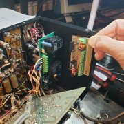
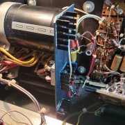
Im almost done breadboarding the 700W upc1235 chip version.
I did check the voltage drop circuit powering only the chip. OK perfect at 55VDC. Same as 400w relay board.
I already did the cap mod, and a few rewirings. The 1237 chip is on a separate small board to start the verification process, will be mounted on the side...Im getting the small caps next week for that board. Then...Ill interface it with the standard 700 w relay board I purchased. The 3 transistors there do all the level shifting, just removing a few resistors and caps. See the attached files.
I did tha cap upgrade...using the old plate, cut in half for no contact to the Hot side of the caps. Those insulators arced over! Added a few small heatsinks for the Bridge cooling...to get some cooling back on smaller board.
Just having fun fixing up my old amps.
Attachments
-
 1.4 MB Views: 60
 -
 966 KB Views: 61
 -
 1.3 MB Views: 61
- Joined
- Jan 14, 2011
- Messages
- 74,494
- Location
- Gillette, Wyo.
- Tagline
- Halfbiass...Electron Herder and Backass Woof
George,
It's not to late to buy the blank 400 board so you don't have to fool with perf board.
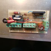
The first and third photos show two small electrolytics on the outputs. Their date code is 7251 as in the week before Christmas in 1972. They're over 50 years old now. Who says electrolytics don't last very long. It's also possible they dried out and opened up 40 years ago and nobody knew the difference.
It's not to late to buy the blank 400 board so you don't have to fool with perf board.
The first and third photos show two small electrolytics on the outputs. Their date code is 7251 as in the week before Christmas in 1972. They're over 50 years old now. Who says electrolytics don't last very long. It's also possible they dried out and opened up 40 years ago and nobody knew the difference.
George,
It's not to late to buy the blank 400 board so you don't have to fool with perf board.
The first and third photos show two small electrolytics on the outputs. Their date code is 7251 as in the week before Christmas in 1972. They're over 50 years old now. Who says electrolytics don't last very long. It's also possible they dried out and opened up 40 years ago and nobody knew the difference.
I use a "form C" relay in both boards.
Relay contacts come in 3 common configurations. The "normal" state is de-energized or shelf state. A form "A" contact is normally open (ANO). it is closed when the amp is turned on. A form "B" contact is normally closed (BNC). It's contact is open when the amp is on. A form "C" contact has a common terminal and one ANO and one BNC. Phase Linear used a form A (normally open).
I use a Form C contact on each channel. Here's why. The common failure mode of an amp is to dump 80-100 VDC into the speaker. A circuit detects DC and tells the relay to open. When the relay tries to open, there is high current flowing through the contacts and the contacts arc. With DC, the arcing welds the contacts. The form C relay uses the normally closed contact to short out (crowbar) the speaker . The relay could fail but that's ok if it protects the speaker.
Common: Connects to?
NO: Connects to?
NC: Connects to?
The configuration of the contacts may seem confusing at first glance. However it adds additional speaker protection that most other designs don't consider. The schematic is attached for convenience
Relay contacts are provided in 3 classes. Normal is defined as shelf state/de-energized.
N.O. = normally open or Form A
N.C. = normally closed or Form B
Both contacts with a common connection = Form C
The relay board uses form C contacts
On the relay board, the common terminal binding post (BP1 & BP3) connects to the speaker. The normally open (N.O.) (J1:A & J2:A) connects to the amplifier output. The normally closed (N.C.) (BP2 & BP4) connects to ground.
At powder up there is a short delay before connecting the speaker to allow the amp to stabilize. This avoids the turn on thump which is actually a DC pulse. When the detection circuit trips, or AC power is turned off, the relay disconnects the speaker from the amplifier.
Very few relays have a DC contact rating greater than 30 VDC. None would fit inside the amplifier, much less on a circuit board. The reason is the contacts arc when opening. If the signal is AC the arcing stops when the current transitions from positive to negative or negative to positive with a normal music signal. In other words the current stops at the zero crossing.
When there is DC on the output due to amplifier failure the arcing doesn't stop until fuses blow. The relay N.C. contact shorts out the speaker. It is conceivable the relay could weld closed. And that's ok because the goal is to protect the speaker.
I've not seen any other manufacturer use a form C contact. They use form A. I've seen welded contacts on receivers and amps that likely damaged speakers.
Attachments
-
54.2 KB Views: 23
Thank you for the clarification.
If the relay is closed, and there is a fault, the relay will open (and there could be the possibility of arcing). If there is arcing, as the relay begins to open and plasma forms (the arc), it will continue until the common contact now gets grounded, extinguishing the arc?
If the relay is closed, and there is a fault, the relay will open (and there could be the possibility of arcing). If there is arcing, as the relay begins to open and plasma forms (the arc), it will continue until the common contact now gets grounded, extinguishing the arc?
- Joined
- May 4, 2016
- Messages
- 408
- Location
- Northeast Iowa
- Tagline
- Love great audio, beermaking and pyrotechnics
Thank you for the clarification.
If the relay is closed, and there is a fault, the relay will open (and there could be the possibility of arcing). If there is arcing, as the relay begins to open and plasma forms (the arc), it will continue until the common contact now gets grounded, extinguishing the arc?
If the relay is closed, and there is a fault, the relay will open (and there could be the possibility of arcing). If there is arcing, as the relay begins to open and plasma forms (the arc), it will continue until the common contact now gets grounded, extinguishing the arc?