J!m
Veteran and General Yakker
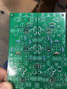
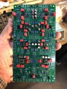
So, about a year ago, I purchased a set of two boards to build both a MC and MM version phono preamp. But when I finally got around to doing something, I discovered a LOT had happened while I was away...
The design is by (Dr.) Wyn Palmer, who, in a former life, designed IC chips. So, this exercise was partly as a slap in the face of all the audiophools, when he decided to design and build a preamp that not only kicks serious ass of some serious preamplifiers out there (including some well regarded big buck ones by famous makers who will remain nameless D'agostino) but uses "normal" components and a CHEAP switching power supply!
Original link: (Version 1) High gain opamp based preamp for low output MC cartridges. | Audiokarma Home Audio Stereo Discussion Forums
(Version 2) Ultra high spec. opamp MC/MM phono, warp "elliptic" filter, line, headphone amps. | Audiokarma Home Audio Stereo Discussion Forums
Link on the builds: The Official "Build" thread for the WYN Phono,Line,Warp,Headphone Pre amp | Audiokarma Home Audio Stereo Discussion Forums
He also did a nice headphone amp I am considering for a later build. I suspect it will be much more resolving for my monitoring needs... (info on that in the Version 2 thread)
The highest attention was placed on getting the RIAA exact. And the deviation from ideal, is less that .3dB in any case as I recall (but I may be off on that), but suffice to say, the most accurate RIAA EQ as compared to several other well regarded (and expensive) phono preamplifiers that he tested. Several Audiophiles, with very expensive preamps, have sold them to be replaced by Wyn's design.
That's the good.
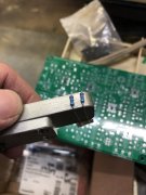
The "bad" news is, the board is (ideally) built to suit a cartridge. The loading and capacitance are adjustable (but generally fine left unpopulated) but the gain is set by a series of resistors in key locations in the circuit. They have to be carefully considered to retain the high accuracy of the RIAA. But, the frequency response is very flat from DC to ultrasonic. And, although it could be billed as "analytical", what you get is what you have. In other words, it doesn't add (or subtract) any "flowery" tube distortion, or enhance or soften any frequencies across the audible band (and beyond). What goes in, gets accurate RIAA correction, is amplified, and passed on down the line. (NOTE: One builder has done some heavy modification with a rotary selector for cartridge loading, and there are a host of other "mods" for this thing). Due to simplicity, the component selection is QUITE CRITICAL in some key places. Not expensive audio-grade components, or beer-can sized capacitors. Everything is carefully considered, and rational, based on science and testing (as well as , of course, listening!). Because of this, some of the components are often out of stock (I purchased from three vendors). But, in some cases tighter-tolerance components are available, and fine. One capacitor value is a 1% version and out of stock. But next week it'll be something else I'm sure...
For my build:
I am doing a two-box (power supply external), two-mode version. I will have two boards inside (plus the power smoothing board): one for MC and the other for MM. There will be four buttons on the front: MM/MC select, 10dB gain, Mono/stereo, and Elliptical Filter. The filter is a simple design that accounts for record "warp", where a very low frequency is transferred to the speakers. Sometimes you may see this as woofer excursion during the warp travel. Anyway, this filter simply eliminates this low frequency information, without any side effects at all. You loose zero music information. Its design is based on similar filters used on cutting lathes and in empirical testing, it works fantastically. A switch is really not needed at all, honestly, but it is switchable, so I'm switching it. If you saw my dumpster-dive records, you probably wouldn't bother with a switch either...
The component cost for my build is $365.24, plus ~$15 for the boards. A build box is needed for the preamp and (in my case) outboard power supply. (everything can go in one box provided the PS is shielded from the boards). I figure another $150 for build boxes. Under $550 for a world-beater. Building a single board would be much less obviously, as would eliminating some of the features the later board incorporates. And the external box is not needed either. This can be built quite inexpensively if it is a single-mode, dedicated unit in a single box (as originally designed). Believe it or not, the design does not get any traction on DIY audio, but, that's their loss!
If you like vinyl and building stuff, get on the band wagon! Wyn is a saint, and very helpful with technical problems too. It doesn't get any better!

