You are using an out of date browser. It may not display this or other websites correctly.
You should upgrade or use an alternative browser.
You should upgrade or use an alternative browser.
Toasted 400 still toast
- Thread starter roccus
- Start date
roccus
Chief Journeyman
Based on your measurements, you are looking good. Get the bias dialed into 0.35V...
BTW, this was your original problem that you just fixed.
Live long and prosper my friend...
I am not so sure this was the original problem could have been part of it?? When the problem first showed up I could run the amp but only at low volume the DCP contacts would stay closed untill I turned it up then the DCP would open. In this case the Contacts just popped even with no input. After I did the original repair this problem did not show up and when I sent the board to you it did not show up. It was not untill I took the DBT out and put full voltage to it did this show up. But it seems ok now, I have run it several hours now and got the bias at .3504 on one side and .3505 on the other side. I can't really push it to hard now on these bose 301's I have it connected to right now and will not move it out to the shop with the big speakers probably till the end of April at soonest when it warms up a bit. For now I will run it the rest of the day then check the bias a final time and button it up.
- Joined
- Jan 14, 2011
- Messages
- 75,928
- Location
- Gillette, Wyo.
- Tagline
- Halfbiass...Electron Herder and Backass Woof
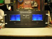
Black faceplate goes well with the blue L:ED's....nice...
roccus
Chief Journeyman
Thanks Lee I think joe has light blue LED's as well these are the dark blue I often wonder if it would look better with the light blue, those handles on it are from Perrys first batch. I got the chassis and face plate from Ron wire from Dennis meters from a parts amp I got off ebay and the rest from JoeBlack faceplate goes well with the blue L:ED's....nice...
- Joined
- Jan 14, 2011
- Messages
- 75,928
- Location
- Gillette, Wyo.
- Tagline
- Halfbiass...Electron Herder and Backass Woof
Lookin good...
VSAT88
Veteran and General Yakker
Damn thing looks nice ! Been following you here to try and learn a thing or two. I am glad you got her up and running !
roccus
Chief Journeyman
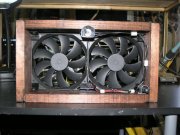
Yea they look good but I like air to circulate when I crank it up... I don't even put the output covers on. I built a cooling fan set up to use when I crank it up nothing fancy but it works wellAnd I'm the only one here who thinks it would look even better in a wood cabinet! Heh...Heh..
Congrats, be happy.

400 looks good with those rack handles.Here it is all finished....
View attachment 33808
silver_face
Journeyman
- Joined
- Feb 18, 2018
- Messages
- 216
- Location
- Southern Indiana
- Tagline
- ---6 and 7 days work week, no end in sight
I have been fallowing this thread for a while, glad you got it going.
Series I 400's look great with rack handles, I got series II style rack handles on mine...…..
Series I 400's look great with rack handles, I got series II style rack handles on mine...…..
roccus
Chief Journeyman
I have been fallowing this thread for a while, glad you got it going.
Series I 400's look great with rack handles, I got series II style rack handles on mine...…..
I liked the looks of the 700 handles, at the time I was building this Perry had some real nice reproductions made so I was able to get a pair and happy I did....
wattsabundant
Chief Journeyman
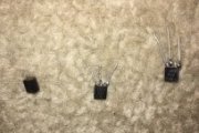
So the smoking gun appears to be the three transistors. Were they tossed in the trashcan? If they are still lying around I’d like to get a hold of them and check them on a curve tracer and post the results.
roccus
Chief Journeyman
Yep still have them laying in a tray but the leads are short not sure if you will be able grab onto them as I cut the leads to make it easier to remove them, you might be able to solder some lead wire on them... pm me your address and I will send them to youSo the smoking gun appears to be the three transistors. Were they tossed in the trashcan? If they are still lying around I’d like to get a hold of them and check them on a curve tracer and post the results.
wattsabundant
Chief Journeyman
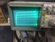
Roccus sent me the old transistors. The leads were less than 1/32" long so I had to solder on extensions. This would be a challenge on a good day, let alone the day after 10 hours of NCAA tournament games at the pub. I could not attach a lead to the one on the left so only two of the three could be tested. I first tested them with an automated instrument that identifies the pin out and measures gain. Both had a gain of 101. I then put them on a curve tracer which is shown in the pircture. That's what a good transistor should look like. Last I used a test set I made to check VCEo, (voltage from collector to emitter with base open). Both were in the 400V range. Summry: 2 of the 3 tested good. I can't draw any conclusions on the third. Given that the amp met Joe's criteria (load sharing) after replacement it would seem the third one may have been the culprit. 


roccus
Chief Journeyman
The leads are short because I cut them to remove the component then heat the leads to extract them from the board for the replacement.... that one you mention with the lead you could not solder to.... I looked at that real close to me it almost looks like it snapped or broke off meaning the transistor may have been ok but if a lead broke off then I would think it would cause problems. The amp seems to running ok now but I have not pushed it yet it is in the house on the bench still connected to a pair of Bose 301's.... in about a month when it warms up I will be moving the amp out to my big system in the shop and then will be able to put it through it's paces... if all is well then the DCP will not cut out when I crank it up, that is what the initial problem was


