The Phase Linear 400 Guinea Pig

laatsch55

Administrator,
Staff member
Joined
Jan 14, 2011
Messages
75,593
Location
Gillette, Wyo.
Tagline
Halfbiass...Electron Herder and Backass Woof
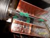
The 400 that got the copper heat sinks on one side was a non-worker on the right channel. Q4 (MPSA-93) was toast, it now is behaving and it is the best example I've gotten of a stocker yet so the AP is gonna have it's way with it to generate some more baseline data.
 

Attachments

  • 100_1104.JPG
    100_1104.JPG
    712.7 KB · Views: 257
Freq response(sucks) 150 mv input , 8 ohm load, DC offset-8mv left, 6mv right. Bias 385 left and right.
 

Attachments

  • 100_1106.JPG
    100_1106.JPG
    680.4 KB · Views: 183
  • 100_1105.JPG
    100_1105.JPG
    707.4 KB · Views: 166
THD & N left channel
 

Attachments

  • 100_1108.JPG
    100_1108.JPG
    693.4 KB · Views: 127
  • 100_1107.JPG
    100_1107.JPG
    717.3 KB · Views: 131
THD & N right channel
 

Attachments

  • 100_1110.JPG
    100_1110.JPG
    673.7 KB · Views: 136
  • 100_1109.JPG
    100_1109.JPG
    730 KB · Views: 131
ya know, it didn't look right to me either. C6 was way out of spec.
 
The others..............
 

Attachments

  • 100_1111.JPG
    100_1111.JPG
    704.3 KB · Views: 142
Just a rough measurement till I can refine the process. Took the same analog thermometers I used last night, applied them with modeling clay, one against the wall, the other on the edge.
Fed the amp on the copper channel, 100watts at 1Khz, at 8 ohms.

I guess it doesn't mean much without a time element.
 

Attachments

  • 100_1115.JPG
    100_1115.JPG
    695.8 KB · Views: 126
  • 100_1114.JPG
    100_1114.JPG
    665.4 KB · Views: 118
  • 100_1113.JPG
    100_1113.JPG
    707.1 KB · Views: 121
  • 100_1112.JPG
    100_1112.JPG
    703.8 KB · Views: 124
After approx 5 minutes it stabilized at 150 and 122
 

Attachments

  • 100_1121.JPG
    100_1121.JPG
    673.5 KB · Views: 119
  • 100_1120.JPG
    100_1120.JPG
    719.5 KB · Views: 115
  • 100_1118.JPG
    100_1118.JPG
    697.6 KB · Views: 112
  • 100_1117.JPG
    100_1117.JPG
    701.6 KB · Views: 109
  • 100_1116.JPG
    100_1116.JPG
    698.1 KB · Views: 107
I'll load it up again, this time with some TIME involved.
 
The line on the far left is the copper HS table for the thermometer against the wall, next to that is the aluminum in the same position. The 3rd row is the copper thermometer at the end of the heatsink, and the 4thg is the aluminum, same place.

What I didn't have is an infrared thermo to check the TO-3 cases. We'll need that to know how effectively the sink is pulling heat away from the tranny case.. Something to chew on till then.

Temp in degrees farenheit.
 

Attachments

  • 100_1122.JPG
    100_1122.JPG
    709.2 KB · Views: 86
Lee,

Are your thermometers touching the heat sink directly or is there a layer of clay in between heat sink and thermometer?
 
Yes Scott they are touching, must be an optical delusion or took the pic before i had the outside one snugged up.
 
Yes, many were fun, and the ones I cannot remember likely were too.

So are you gonna post temps stock fins vs copper?
 
I did Scott. The first line is the copper fin temp. The 2nd is the aluminum temp, the 3rd is the outside copper temp, and the 4th the aluminum outside temp.
Buying an infrared thermo today so we can track the TO-3 case temp relative to the HS temps. Then we'll know.
 
left channel, bias 386Mv, DC offset-6 MV, 100 watt output, 8 ohm load, 782 mv input.

Aluminum heatsink
 

Attachments

  • 100_1126.JPG
    100_1126.JPG
    699.2 KB · Views: 49
  • 100_1125.JPG
    100_1125.JPG
    660.9 KB · Views: 48
Back
Top