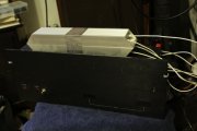
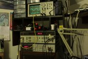
Testing WOPLS "automated" by Jer...

jbeckva

Admin/Server Dude MAA Guy
Staff member
Joined
Jun 11, 2010
Messages
6,849
Location
Powhatan, Virginia, United States
Tagline
WassupYa Mang?
#1
LOL so like in Sutt's 700 build thread I alluded to playing around with an IEE-488 GPIB controlled testing platform, based on the HP8903A analyzer. Was thinking if I needed to also include the HP3455A multimeter, but I'll cross that bridge when it comes.

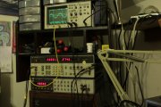
So basically, so far what I've done is to create a little program that sends the appropriate commands, measures, etc. The first challenge was to figure out how to actively measure the voltage gain RATIO for the amp under test. Since this is a fixed and linear value, in theory I could use it to calculate the appropriate signal input voltage for whatever I needed on the output. And it works here.. (pressed the amp gain button, the results are shown in the readout on the bottom)

T01-AmpGain.JPG

How do I know this is accurate? Well from there, I was able to calculate the appropriate input voltage for a "specific" power output by first calculating what actual output RMS volts was required for the specified wattage..

E (out) = SQRT(P x R) where E is the voltage needed, P is the power in watts desired, and R is the dummy load resistance (8 ohms in my case).

Once E (out) is known, E (input) is calculated by dividing the output voltage desired by the amp gain already precalculated in realtime and specific to the amp being tested.

And here's the result.. I wanted 55 watts.. the 8903A is capable of such a measurement..

1552670703516.png

Going to one watt, even closer.. close enough for my purpose!

1552670754841.png

And.. hell.. here you go. This is from my other WOPL which is a converted 400. Not too shabby considering ..

Watts..

1552670916877.png

Distortion at said watts..Mind you, this is one channel loaded due to the 700 whacking one of my dummy loads so it's conceivable ...

1552670982760.png

So the next challenge will be to write a routine that will (slowly but surely) increase the power output until the associated distortion measurement reaches.. say.. .5 percent. That should be a good indicator of the amp's single shot power capability.

More to come...this is FUN...
 

jbeckva

Admin/Server Dude MAA Guy
Staff member
Joined
Jun 11, 2010
Messages
6,849
Location
Powhatan, Virginia, United States
Tagline
WassupYa Mang?
#3
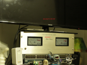
Alrighty then.. so now we're back in business with 1000 watters that I would hope won't shoot fire out the ends. Also meet "NoFace" here LOL, which is a 400 WOPL build, fronted by an old 700 faceplate from a long forgotten build (but whoever recognizes it, feel free to speak up).

PT-BIGDUMMY.JPG

I found the clip point to be, with both channels driven (and 8 amp rail fuses!) .. around 302 before distortion started to creep up from an average level of .07 or so.. Watts shown here..

PT-300W.JPG

And distortion for the same output.. it would climb up fairly quick from 302. Now what I need to do is capture it, plot it, and display it. Checking into some .NET controls that should do the trick. I haven't had the need to explore em until now, so it's a new thing to learn. Stay tuned for some cool graphs and whatnot. I hope.. lol..

PT-300WDIST.JPG
 

jbeckva

Admin/Server Dude MAA Guy
Staff member
Joined
Jun 11, 2010
Messages
6,849
Location
Powhatan, Virginia, United States
Tagline
WassupYa Mang?
#5
Working good, Lee. I just programmed in the "test" where I tell it how many watts to start with, how many to increment and at what level of distortion to stop. Both channels registered 305 (2Khz) at the .9 percent mark so figure yeah 305 at clipping.

Now for Ed.. here you go, and this is with a 400 WOPL. 20Khz @ "rated" power of 210 watts. Now also what was very interesting is that when I went to 20Hz from 1Khz (I power it up initially at 1K then issue that frequency change command), the DCP kicked in. At 20Hz I had to start low, around 100 watts then after setting it to 20Hz bump it back up to rated power. Well. at least we somewhat know that the DCP will do it's job, but yeah with "NoFace" here, the DCP is a bit funky ... will eventually get around to fixing it.

Anywhoo.. here's the spread..

20Khz

1553391641592.png

10Khz

1553391740222.png

5Khz

1553391819718.png

1Khz

1553391906859.png

100hz

1553391971867.png

And 20Hz (8903A's gen can't go past this.. sorry!)

1553392366671.png

I'd like to do the damping factor test next. But keep in mind that means two measurements like Ed said.. one with it loaded the other unloaded. That is where I JUST might go find the next IEEE-488 enabled test component.. something like this here to switch loads in and out, etc...

https://www.ebay.com/itm/HP-Agilent...-Switch-Control-System-Mainframe/281970015171

Ayee.. insanity at it's finest. I feel the mad scientist vibe pretty strong LOL
 

jbeckva

Admin/Server Dude MAA Guy
Staff member
Joined
Jun 11, 2010
Messages
6,849
Location
Powhatan, Virginia, United States
Tagline
WassupYa Mang?
#6
Ok.. damping.. hmmmm...

Well, my loaded voltage reading was actually higher than the unloaded reading.. Joe how's that possible? :)
(yeah probably test equipment hehe)..
 

jbeckva

Admin/Server Dude MAA Guy
Staff member
Joined
Jun 11, 2010
Messages
6,849
Location
Powhatan, Virginia, United States
Tagline
WassupYa Mang?
#9
ps.. All this testing indicates that at least for this guy, I have some work to do on the right channel. Distortion on that channel was a tad higher than the left. Eventually.. that and the DCP. In any case, overall it sounds damn good like a good WOPL should LOL.
 

oldphaser

Chief Journeyman
Joined
Sep 8, 2012
Messages
848
#14
Now for Ed.. here you go, and this is with a 400 WOPL. 20Khz @ "rated" power of 210 watts.

20Khz

View attachment 34313
Jerry,

Is the result noted above for single channel driven or both channels driven? I would expect to see (2) THD figures that are not exactly the same.


THD spec for a 400 series 1 amp is .25%.
A 400 series 2 is .09%.

So if you were using the same pc board in a series 2 amp it would not meet factory spec.

By the way, I have an old PL400C pc board in a 400 series 1 amp which I stripped down and re-populated the board with carbon film resistors, newer Nichicon caps and MJ series output transistors. The amp with both channels driven at rated output at 20kHz will do .073% THD in the left channel and .057% THD in the right channel.

It should also be noted that THD levels will change dependent upon the duration of test. In other words, heat will affect the results. The IHF-A-201 (1968) called out for 30 seconds. With the next revision: IHF-202 (1978) it became 5 minutes as is also in the current CTA-490-A R2008 standard. The FTC standards did not allow for the use of fans unless the amplifier came equipped with fans at the point of sale.


The Phase Linear 400 series 1 was initially rated at 200 watts per channel then increased to 201 watts after the release of the FTC spec in November 1974.

The 400 series 2 was rated at 210 watts per channel.


As for damping factor, obviously a higher resolution and accuracy multi-meter will also provide more meaningful results than a lower resolution meter. Play with the numbers by say .01V and then .001V in your calculations and you will see significant differences. Unfortunately for me, my meter reads only to .001V up to 20V and .01V thereafter. With a relay installed, I do not expect you to see a damping factor of 1000:1. More likely around 200:1.

The 400 series 1 damping ratio spec is 1000:1 at 20Hz.
NOTE: Phase Linear also did this for the original 700 series 1. However with the 700B, the damping ratio was initially rated at 20Hz in sales brochures, owner's manuals and early service manuals, then eventually 1kHz (as is noted in the 700/700B 2/81 revision of the service manual).

The damping ratio spec for 400 and 700 series 2 amps is 1000:1 at 1kHz.
NOTE: This does not include the PRO700 which had a lower ratio at 1kHz of 330:1.

Ed
 

jbeckva

Admin/Server Dude MAA Guy
Staff member
Joined
Jun 11, 2010
Messages
6,849
Location
Powhatan, Virginia, United States
Tagline
WassupYa Mang?
#16
Hey why would you want to use carbon resistors in leiu of the metal film types? I've done a few reworks with the MF's which drastically cut the residual noise in the circuits. Ole Larry used to say "resistors make noise" (something like that), and after scoffing a few times I tried it out on a Carver pre ... big diff! Guess it might depend on the overall design tho, but so far it's been a good idea for me.
 

oldphaser

Chief Journeyman
Joined
Sep 8, 2012
Messages
848
#17
Jerry,

I have long recognized that the specs on metal film resistors are better than carbon film or carbon composition resistors.

In order to compare Phase Linear amplifiers with different pc boards in them, I didn't want to stray too far afield from what components Phase Linear would have used during their time in Washington state. Phase Linear also started using carbon film resistors in earnest around 1974.

At some point I will populate some pc boards with metal film resistors and better grade caps and see what differences they make in my measurements as well.

From the standpoint of signal-to-noise ratio, it is ironic that the quietest amps that Phase Linear ever made were the original 700 with PL0171 pc board and 400's with the PL400C pc board. These amps had carbon composition resistors in them.

I also started a new thread on resistor noise:
https://forums.phxaudiotape.com/threads/resistor-noise.8704/

Ed
 
Last edited:

jbeckva

Admin/Server Dude MAA Guy
Staff member
Joined
Jun 11, 2010
Messages
6,849
Location
Powhatan, Virginia, United States
Tagline
WassupYa Mang?
#18
Yeah Ed, was wondering.. metals do make a huge diff in some instances LOL.

Anywhoo.. so earlier today I found out I need a new water heater (insert expletive here, oh well..). It's in this room right behind Frankey and the TV, so .. was a good time to switch amps and put Frankey on the bench. Now mind you.. one channel driven as I don't necessarily want to be tripping breakers.. but anyway.. here's the rampup on peak power.. 520 seems to be the last reading before the distortion began to rise. Overall, not bad.. but let me go take a few shots of Absinthe to steady the nerves before driving both channels LOL.

Now a question.. I have two low pass filters that I can switch in for the reading. The below metrics are with no filtering, but yeah if I do put the 30Khz low pass filter, then at higher freqs the readings are much lower. So does that mean that the analyzer is seeing harmonics at higher freqs or is it common to have a low pass filter "in" when measuring?

ps I surely can NOT imagine actually listening to it anywhere near this level. The meters were buried and that is kind of expected since they really are set for a 400 (via Joe's 400 light board), but seriously.. if I even attempt to max Frankey out in actual listening, with these D9's I might just turn into Ron.. or Lee LOL hahahah.. don't know how you guys do it man. It sure is good to know that I can make the guy two doors down shut his friggin car stereo off as that has been done.

Frankey, one channel driven, 1Khz with 10 watt increments....

Output at 300 watts ...0.1421 percent.
Output at 310 watts ...0.038 percent.
Output at 320 watts ...0.0374 percent.
Output at 330 watts ...0.0378 percent.
Output at 340 watts ...0.0382 percent.
Output at 350 watts ...0.0389 percent.
Output at 360 watts ...0.0398 percent.
Output at 370 watts ...0.0414 percent.
Output at 380 watts ...0.042 percent.
Output at 390 watts ...0.0432 percent.
Output at 400 watts ...0.0443 percent.
Output at 410 watts ...0.0452 percent.
Output at 420 watts ...0.0465 percent.
Output at 430 watts ...0.0478 percent.
Output at 440 watts ...0.0496 percent.
Output at 450 watts ...0.0523 percent.
Output at 460 watts ...0.0541 percent.
Output at 470 watts ...0.0396 percent.
Output at 480 watts ...0.0414 percent.
Output at 490 watts ...0.0437 percent.
Output at 500 watts ...0.0442 percent.
Output at 510 watts ...0.0448 percent.
Output at 520 watts ...0.0615 percent.
Output at 530 watts ...0.501 percent.
Output at 540 watts ...1.148 percent.
 

laatsch55

Administrator,
Staff member
Joined
Jan 14, 2011
Messages
74,827
Location
Gillette, Wyo.
Tagline
Halfbiass...Electron Herder and Backass Woof
#19
Anytime you limit the bandwidth you are cutting out harmonics and noise. I try to go 10 to 80K unfiltered , then IEC -A weighted from 22-22K...Joe throws in the 30K top filter.....seems we all have a different set of numbers...
 

Gepetto

Administrator
Staff member
Joined
May 15, 2011
Messages
13,944
Location
Sterling, MA
Tagline
Old 'Arn Enthusiast
#20
And they are all good Lee. I use both the 80K and 30K filter Jer. The 30K just cuts out extraneous HF noise supersonic to the audio band. You can probably get close with the 80k filter but it takes great care with all your test equipment leads and setup.

You will even see a similar measurement difference when you directly feed the output of the 8903B back into the input without an amp in the middle.
 
Top