- Joined
- Jan 14, 2011
- Messages
- 75,601
- Location
- Gillette, Wyo.
- Tagline
- Halfbiass...Electron Herder and Backass Woof
2009 was a very good vintage....

You have modern manufacturing methods like CNC machinery and extreme improvements in materials consistency on your side.Ok - then I will roll the dice and hope for the best.
Good times... Back in the pre-WOA days.I do remember you and i matching TIS -97's on the stockers...
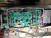
At the RCAs, consider removing the copper grounding plate and isolating them from chassis ground with fiber washers.
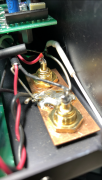
What did you do with the white wire?As I was soldering the wires to the PL14_20, I pulled the ground wire back and cut it after taking the above picture.
Al, I call the white wire the "White Wire of Death". Some on the forum will disagree (and that's OK), but I was taught never to connect the grounds of the inputs to the grounds of the outputs. Your inputs are properly grounded when you run the two wires (signal and shield - from the RCA jack nomenclature) to Joe's Control Board. You don't need that potential ground loop caused by the white wire circling back to the star ground.
These are the nine wires that I connect to the Star ground:
1. Left Speaker Ground
2. Right Speaker Ground
3. Chassis Ground
4. Faceplate Lighting or Cylon Meter Ground
5. DCP Relay Board Ground
6. Left Backplane Ground 1 (if installed)
7. Left Backplane Ground 2 (if installed)
8. Right Backplane Ground 1 (if installed)
9. Right Backplane Ground 2 (if installed)
Can't do that, them caps are OLD......385 is nominal on bias....no reason NOT to have it there...it's too easy to make it stay...