Sutton's Phase Linear, White Oak 500

Skratch

Chief Journeyman
Joined
Dec 27, 2011
Messages
1,130
Location
Huntley Il.
Tagline
Life is short, so take your time
Installed the Phoenix terminal connectors on the WO board. Will install it tonight, took all readings with all the old components in it and going to compare with all the new stuff.
 

mlucitt

Veteran and General Yakker
Joined
Jun 24, 2011
Messages
3,373
Location
Jacksonville, FL
Skratch, after checking five boards, I only ever found one terminal that was not making contact and it happened to be 12R, which has no wire connection to the terminal strip anyway.

Good Luck,

Mark
 

Skratch

Chief Journeyman
Joined
Dec 27, 2011
Messages
1,130
Location
Huntley Il.
Tagline
Life is short, so take your time
Mark Ohmed out all connections and no problems. I had to tilt it a little to keep it away from D13 and R23. Do you put the jumpers on the back or put jumpers on 5,11,12
 

mlucitt

Veteran and General Yakker
Joined
Jun 24, 2011
Messages
3,373
Location
Jacksonville, FL
Yes, mine is tipped slightly. I put the jumpers on the back because Joe told me to. Actually, I think the insulated buss wires on the back are an elegant solution and should never cause a problem.
 

mlucitt

Veteran and General Yakker
Joined
Jun 24, 2011
Messages
3,373
Location
Jacksonville, FL
Did you install the Gepetto Mod? (diode pair on C6L and C6R). Lee puts them together and I put one on each side of the cap terminals. Just curious how you did it.
 

Skratch

Chief Journeyman
Joined
Dec 27, 2011
Messages
1,130
Location
Huntley Il.
Tagline
Life is short, so take your time
Yes I put the diodes across C6. Mark, when you check conductivity on the terminal strip,a standard Fluke tip is just a hair too big and sometimes its hard to get it in. I used a clipped resistor lead and an alligator clip that way you can get it in the terminal. The holes are plated through so your solder on the back should be all you need ? Also, I was looking at the print and was wondering what Boost+ was. There is no connection to it, might be some future upgrade.
 

mlucitt

Veteran and General Yakker
Joined
Jun 24, 2011
Messages
3,373
Location
Jacksonville, FL
I touch to the screw on top of the terminal and if there is continuity there, it is everywhere. But I like your ingenuity. Yes, I had solder on the back of that board but I had to reheat it five times before it flowed to the top of the board where the trace was - very unusual.

Joe can chime in on the Boost+. That had me going in the begining until Joe told me it was for future use. I was thinking maybe the Series II. There are other connections such as 16L to 16R and the components that are not used, D14L and D14R, R70L and R70R, and R71L and R71R, etc.
 

laatsch55

Administrator,
Staff member
Joined
Jan 14, 2011
Messages
74,240
Location
Gillette, Wyo.
Tagline
Halfbiass...Electron Herder and Backass Woof
Joe is, I've found out, 4 or 5 steps ahead of us. What kills me is how long he can keep these secrets.
 

ksrigg

Chief Journeyman
Joined
Jul 28, 2011
Messages
1,451
Location
Wise, Virginia
Lee,

All Phase Linear amps, Tara Labs iCs, fans, everything has landed. Everything appears to be in good shape except the meters on the 400 with 8 heat sinks. The meters came completely apart, and I'm fishing all the pieces and parts from inside the chassis to put them back together. I've never seen meters like these ! At first I was confused, because I saw the tape and little hole in the tape (where you adjust the meter?) right in the center of the meter glsss. Didn't look right, so I took the faceplate off and found the pieces down in the amp. Question....the four aluminum tabs go where? under the screws holding the meters in place? I still do not have everything installed, I wanted to make sure there is nothing which might have come loose in travel, but tey look like they made it with no corner bends, etc..

The 700B is a beauty! I can't wait to have everything in place and the whole system put together. I will do it probably either tomorrow, or over the weekend with a little help from Kev, I hope...

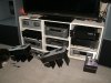
They look fabulous.....just fabulous....and when I get through, the rack will be filled with Phase Linear amplification....Eventually the two 700B's, and four 400 Series I's...In the middle I will have the pre/pro/ Onix, Directv, and Blu-Ray player...I'm thinking I may place the two Belkin power conditioners behind my TV so I can hit the switches for power up, while not using a rack space....(I'm out of space)

Absolutely gorgeous work Lee, inside and out. Your work is simply perfect. Makes me feel pretty pathetic when I see how a pro does it.


Again, thank you, thank you, thank you......soooooo much...

The little black dog is Bear.....he is checking Jazz out I think...
 

Attachments

ksrigg

Chief Journeyman
Joined
Jul 28, 2011
Messages
1,451
Location
Wise, Virginia
What is the verdict for output transistors for a WOPL 400?

MJ21196G

or

MJ21194G

and for sriver transistor I am guessing the best for this application is

MJ15024G

I'm making a Mouser order, and just want to try to get everything I need. Seems I find there are more and more things I need each order.

and Lee, for minigrabbers or for use in the PL should I order Mouser 565-6231 or is there a better alternative?
 

laatsch55

Administrator,
Staff member
Joined
Jan 14, 2011
Messages
74,240
Location
Gillette, Wyo.
Tagline
Halfbiass...Electron Herder and Backass Woof
Yes Sutton the 4 aluminum tabs go under where the hold down screw arm holds to the meter. the aluminum tabs were meant to spread the load on the meter housing so they could be tightened enough so that they wouldn't move during shipping. Blew that theory didn't it?? Still a good idea, so I won't abandon it.
I am glad you think they are worth keeping, that was the object.
BTW--they sound fabulous.
 

laatsch55

Administrator,
Staff member
Joined
Jan 14, 2011
Messages
74,240
Location
Gillette, Wyo.
Tagline
Halfbiass...Electron Herder and Backass Woof
15024's as drivers and (Mark will argue with me here) 21194's as outputs, but only on the 400. The 700 I am now putting in 96's, NOT 94's. Mark proved his point on the 94's in the 700 application. They are on the ragged edge.
 

Skratch

Chief Journeyman
Joined
Dec 27, 2011
Messages
1,130
Location
Huntley Il.
Tagline
Life is short, so take your time
3/4 x1 x 1/16 and I super glue them that way if they loosen up they don't fall and possibly short something out. Also I finger tighten the allen screws and put a little super glue on the thread to keep them from loosening.
 
Top