You are using an out of date browser. It may not display this or other websites correctly.
You should upgrade or use an alternative browser.
You should upgrade or use an alternative browser.
PL700 Rebuild
- Thread starter Overundr1
- Start date
mr_rye89
Veteran and General Yakker
IDK my 700B (1976 build date) had RCA 66546s as the drivers. I'm not sure what a modern sub would be (aside from full comp conversion/WO backplanes)
mlucitt
Veteran and General Yakker
The early Phase Linear amplifiers used RCA 410 Driver Transistors. Later units saw RCA 66546 Driver Transistors, which are the exact same device with a newer RCA part number. These are the only recommended drivers for a Quasi-complementary (in which all NPN power transistors are the same - PL909, XPL909, MJ15024; or the upgraded MJ21196G).
If you need some driver transistors, most rebuild techs on the Forum have some.
If you need some driver transistors, most rebuild techs on the Forum have some.
Problem is, the original output sockets are also past due retirement. And they went through several revisions trying to improve that back wall.
I'd rebuild the back wall complementary like the final Series 2 and Pro's had, with the highest quality sockets you can find, or follow Eric's advice.
Eric's advice is spot on.
Many have had issues with shorts when snugging up those outputs due to bad sockets
The sockets were totally trashed in two 400's and just OK in a 700 Pro, all I full WOPL'd in the original chassis. That 700 Pro was the final late model of the 700 series.
Shame the output spacing is different in the 700 "Series 1". One of the reasons it trades for less $.
But Joe has the solution.
mlucitt
Veteran and General Yakker
George, quite right. I have replaced the original broken sockets for customers that want to keep their amplifiers "original." Gently squeezing the two socket pin receptacles can bring an original socket back to life. Of course using Sil-Pads rather than mica and silicone is also a must for any removed TO-3 transistor. Lastly, the screws should be torqued to 7 inch-pounds and no more. If you don't own a torque screwdriver, you have no business removing any driver or output transistors.
Overundr1
Journeyman
- Joined
- Sep 12, 2024
- Messages
- 195
After spending waaaaay too much time this afternoon cleaning 50 year old thermal paste off the surfaces agree with the silipad comment 150%. And had to smile at the comment about gorilla installed to-3 mounting screws. It’s an amplifier not the Bismarck sheeesh.
- Joined
- Jan 14, 2011
- Messages
- 75,923
- Location
- Gillette, Wyo.
- Tagline
- Halfbiass...Electron Herder and Backass Woof
RCA 410's, I'll send those with the 97's
Overundr1
Journeyman
- Joined
- Sep 12, 2024
- Messages
- 195
Lol, went right back up to shop and looked in vain for the model to hop out of the PL-700 and nothing doing only bunnies I found were dust bunnies 
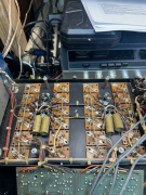
Anyways did a thorough check of the to-3 mounting board, found a hairline crack in one of the to-3 mounts, all the resistors and diodes are fine, but those 4uf 150v Mallory paper caps are absolute toast with both capacitance and esr off the scale. Checked pin tension with a just fit pin drill and they all felt nice and snug. Any reason not to use 4.7uf 250v panasonic ecq films I have in stock in this location?
Cracked socket is bottom row third from left btw.

Overundr1
Journeyman
- Joined
- Sep 12, 2024
- Messages
- 195
Any suggestions for a fifteen pound Maine Coon female that just turned one and has the teenage female attitude issues?
Sheeesh
repeat after me - - -
those are my pliers
those are my diodes
those are my papers
etc etc etc nosey kitty gets into everything
Sheeesh
repeat after me - - -
those are my pliers
those are my diodes
those are my papers
etc etc etc nosey kitty gets into everything
Vynuladikt
Journeyman
- Joined
- May 4, 2016
- Messages
- 471
- Location
- Northeast Iowa
- Tagline
- Love great audio, beermaking and pyrotechnics
My youngest son had a pet racoon years ago. Got into my shop one day and proceeded to knock everything on bench and shelves onto the floor.
Made sure that never happened again. What a mess!
Made sure that never happened again. What a mess!
mlucitt
Veteran and General Yakker
Your Panasonic capacitors would be a perfect fit there.Any reason not to use 4.7uf 250v panasonic ecq films I have in stock in this location?
wattsabundant
Chief Journeyman
There is a misconception that gobs of heat sink grease (post #1) with the mica insulators is a good thing. It is generally accepted that the silpads are preferred. However if mica is used a drop of grease about a 1/4" in diameter between the base emitter pins is all that is needed.
I tighten the TO3 sheet metal screws with thumb and index fingers only. When the nut driver slips in my fingers it's tight. I've never stripped out a socket.
I tighten the TO3 sheet metal screws with thumb and index fingers only. When the nut driver slips in my fingers it's tight. I've never stripped out a socket.
Overundr1
Journeyman
- Joined
- Sep 12, 2024
- Messages
- 195
Thought I would get the input/output jacks sorted out, keeping the relay instructions cloase at hand (and yes have those 8 fiber washers safely stored away). Cannot believe this is factory, they are all 1/4" jacks soldered to a copper substrate that floated above the fiber washers.
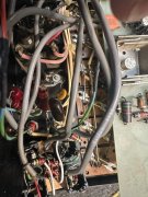
And another view
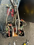
Now with them separated for a close up.
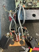
And finally the output jacks. Worth noting there were a pair of 1N4004's paralleled nose to tail between the copper ground plane of the input jacks to the ground buss on the output jacks that you can see at the top of the picture above.
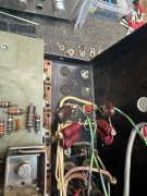
If anyone has a image to share of a clean installation after rework that would be awsome.
The potentiometers cleaned up nicely and now track well so that is done.

And another view

Now with them separated for a close up.

And finally the output jacks. Worth noting there were a pair of 1N4004's paralleled nose to tail between the copper ground plane of the input jacks to the ground buss on the output jacks that you can see at the top of the picture above.

If anyone has a image to share of a clean installation after rework that would be awsome.
The potentiometers cleaned up nicely and now track well so that is done.


