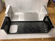
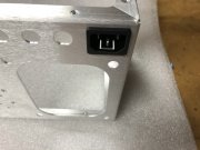
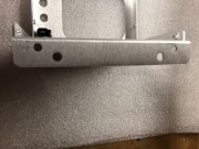
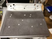
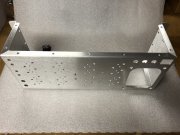
One proto PL400 chassis piece supposed to be in my hands by early next week. Will use to double check CAD design work.
You are using an out of date browser. It may not display this or other websites correctly.
You should upgrade or use an alternative browser.
You should upgrade or use an alternative browser.
PL400 II Chassis Spare Parts
- Thread starter happy_aluin
- Start date
WOPL Sniffer
Veteran and General Yakker
The WO chassis virgins really need to get ahold of one of the chassis. They are the best.
mlucitt
Veteran and General Yakker
Chassis virgins, HUH??? Chassis virgins, that's a good one.
Mohawk
Chief Journeyman
What one are you referring to, the Chassis or the Virgins ? 
WOPL Sniffer
Veteran and General Yakker
Wheel-right
Chief Journeyman
Very nice, yep that'll be number one on my list of parts to build the 400 up.
Mohawk
Chief Journeyman
I'm in !
Hmmm, lots of extra screw holes on the left side chassis wall. At first I thought for terminal strips, but the layout looks weird. I don't know. Hopefully they're there for some big improvement.
I have to be sympathetic to the needs of the 4 fin owners out there that don't have a die cast cradle on the transformer to mount the bridge rectifier and bulk capacitors...some of the holes are needed to support that.
MarkWComer
Veteran and General Yakker
- Joined
- Nov 1, 2014
- Messages
- 3,520
- Location
- Gaston, SC
- Tagline
- Victim of the record bug since age five
And the original 400 meters won’t be so close to the filters- looks a bit deeper.I have to be sympathetic to the needs of the 4 fin owners out there that don't have a die cast cradle on the transformer to mount the bridge rectifier and bulk capacitors...some of the holes are needed to support that.
And the original 400 meters won’t be so close to the filters- looks a bit deeper.
A bit?? An extra 1-3/8" to give you that roominess that is desired...
More pics coming later this week, as I build up some key portions of the proto.
- Joined
- Jan 14, 2011
- Messages
- 75,903
- Location
- Gillette, Wyo.
- Tagline
- Halfbiass...Electron Herder and Backass Woof
Nice, lots of room now!!!
Steve K
Journeyman
Nice!
So, screw holes on the left wall for the non cast cradle units. Still trying to figure out what the extra holes on the left wall are for. The elongated holes are obviously for the S2 intermediate plate that mounts the digital meters. Seems like way too many holes.
- Joined
- Jan 14, 2011
- Messages
- 75,903
- Location
- Gillette, Wyo.
- Tagline
- Halfbiass...Electron Herder and Backass Woof
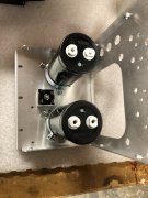
How big are the caps Joe?
How big are the caps Joe?
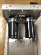
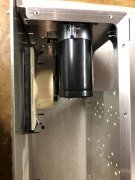
Hi Lee, the design accommodates up to 2" caps if user desired. The samples I put into this photo are 20KuF/100V Kemet caps 50mm x 105mm. If you look hard enough, you may find caps slightly larger than 20KuF from reliable manufacturers. It also accommodates the normal 40mm x 105mm 15KuF/100V caps either transformer cradle mounted or chassis wall mounted with band clamps depending on what generation of original PL transformer you are dealing with.
The extra depth provides the flexibility to allow this degree of customer choice. This is the culmination of all the customer input I have accumulated through the years.
- Joined
- Jan 14, 2011
- Messages
- 75,903
- Location
- Gillette, Wyo.
- Tagline
- Halfbiass...Electron Herder and Backass Woof
20k in a 400 is plenty big.....even for me. .nice job Joe..

