
PL400-700 BABB Pictures
- Thread starter Gepetto
- Start date
Hi Mark
I will take it under advisement and do my best, but it may be very challenging.") View attachment 70878
View attachment 70878
I will take it under advisement and do my best, but it may be very challenging.
View attachment 70878
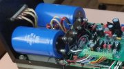
Why won't this work on a 700B/II ????
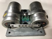
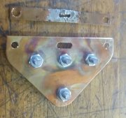
The picture above of the 700B die cast cradle shows the recommended install with the bridge snubber. Bridge moves to the hole for the hold down strap. Replace the original wimpy 6-32 x 1-1/2" screw with a 10-32 replacement. Bore out die cast and strap hole to 0.203" (13/64 or #6 drill). Install 10-32 x 1-1/2" screw protruding from the cradle bottom, install bridge with snubber board, then internal tooth #10 washer, then 10-32 hex nut, then band clamp and finish off with a second 10-32 hex nut. This is what is pictured above.
PS: I will now start including one 10-32 x 1-1/2" SS screw, one #10 internal tooth SS lock washer and two 10-32 SS hex nuts with the bridge snubber kits going forward to make it easy to upgrade your installation to what is pictured above.
PS: I will now start including one 10-32 x 1-1/2" SS screw, one #10 internal tooth SS lock washer and two 10-32 SS hex nuts with the bridge snubber kits going forward to make it easy to upgrade your installation to what is pictured above.
Last edited:
- Joined
- Jan 14, 2011
- Messages
- 74,244
- Location
- Gillette, Wyo.
- Tagline
- Halfbiass...Electron Herder and Backass Woof
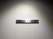
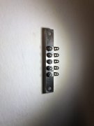
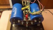
Joe, what is the center to center spacing of the capacitor screw holes? I measure 3.000" on both the PL400 and the PL700B amplifiers. Of course, that depends on the rotational axis of the two capacitors and therefore the terminal screws radial linearity. Mine are at 45 degrees from vertical, plus or minus.
In other words, the Big Ass Bus Bar should work in any PL400, PL700B, PL700 II, PRO700, and the Mighty Dual 500.
Mark
In other words, the Big Ass Bus Bar should work in any PL400, PL700B, PL700 II, PRO700, and the Mighty Dual 500.
Mark