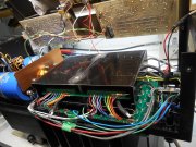
Hi M, I have just finished the input wiring and will test the noise level next. I forget who may have commented on my AC wire routing but have a faint memory of someone mentioning that this was the original method, (not sure). My thoughts are that since the input is at the bottom of the board and the Op amp is at the top, nowhere is best.
I have not checked but as this is a multi layer pcb, the input signal pcb trace may not necessarily be on the bottom face. Could you confirm this Joe?
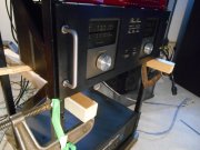
By routing the wiring at mid level latitude, I could leave the top of the "faraday cage" open to alleviate cooling issues for the PL14_20. I will test this amp for noise first, to see if the steel shield is needed at all.

")