PL 700 II Clair Bros Rising from the Ashes

WOPL Sniffer

Veteran and General Yakker
Joined
Aug 10, 2015
Messages
11,522
Location
Minnie-Soda
Tagline
Screw it
Building the White Oak option is far easier Ed, in addition to providing much higher quality and reliability sockets than the original Keystone sockets. That is why it is offered and that is why nearly everyone chooses this option for conversion.
Joe, it takes me roughly 3 hours to build a back plane kit
 

Peter S

Journeyman
Joined
Jun 29, 2019
Messages
312
Location
Ontario Canada
Thanks for the info regarding rev B and C back planes. I have the rev B's. When doing my noise measurements, I noticed about 1 mV of cross-talk, with the opposite channel being driven to maybe 5 or 6 volts. ( 1 kHz ) I wired the ground from right to left as instructed by the rev B documentation.

I am pleased with the current performance but would running the Right chan ground separately to the Power supply ground bus be a significant improvement?
Bit of a PITA pulling all output devices on the right chan to remove the back plane for soldering. Or would you take extra care and change those wires with the back plane in place?
 

WOPL Sniffer

Veteran and General Yakker
Joined
Aug 10, 2015
Messages
11,522
Location
Minnie-Soda
Tagline
Screw it
Thanks for the info regarding rev B and C back planes. I have the rev B's. When doing my noise measurements, I noticed about 1 mV of cross-talk, with the opposite channel being driven to maybe 5 or 6 volts. ( 1 kHz ) I wired the ground from right to left as instructed by the rev B documentation.

I am pleased with the current performance but would running the Right chan ground separately to the Power supply ground bus be a significant improvement?
Bit of a PITA pulling all output devices on the right chan to remove the back plane for soldering. Or would you take extra care and change those wires with the back plane in place?

We have been running the right channel grounds (Ground 1 and Ground 2) to the copper bus for a while.
 

Gepetto

Administrator
Staff member
Joined
May 15, 2011
Messages
13,944
Location
Sterling, MA
Tagline
Old 'Arn Enthusiast
Thanks for the info regarding rev B and C back planes. I have the rev B's. When doing my noise measurements, I noticed about 1 mV of cross-talk, with the opposite channel being driven to maybe 5 or 6 volts. ( 1 kHz ) I wired the ground from right to left as instructed by the rev B documentation.

I am pleased with the current performance but would running the Right chan ground separately to the Power supply ground bus be a significant improvement?
Bit of a PITA pulling all output devices on the right chan to remove the back plane for soldering. Or would you take extra care and change those wires with the back plane in place?
Significant is hard to quantify from a SQ perspective when it comes to crosstalk. I wish I could hear a millivolt crosstalk difference Peter.

That change is for design purity purposes since the control board went to 2 independent channels, the backplane wiring should logically follow. The ground currents are miniscule on the backplanes as they are only the return currents through the decoupling caps that run through these ground wires. Nothing on the backplanes except that decoupling current and the Zoebel return are ground referenced. You can see that in the schematic.
 

Peter S

Journeyman
Joined
Jun 29, 2019
Messages
312
Location
Ontario Canada
I am starting a rebuild of the second PL700 II and will verify the necessity of the shield.

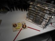
On to a side issue; it has been pointed out that my dummy load (pictured below, ex electric furnace ) may have some inductive properties. The elements were reconfigured to be 8 ohms.
This may be basic electronics, but could I test this by connecting it in series with an 8 or 10 ohm carbon resistor, then measure the voltage at the centre point with my scope? If the voltage does not shift with frequency, would this confirm the suitability of the dummy load?
As soon as my wife is not looking, I will escape to my shop and try this!
 

Attachments

Peter S

Journeyman
Joined
Jun 29, 2019
Messages
312
Location
Ontario Canada
Testing the first WOPL PL700 II for power output resulted in an impressive 450 Watts+ per channel, one channel driven, into my 8 ohm dummy load.
As the dummy load is actually from a retired electric furnace, the coiled elements could have inductive properties leading to false readings.
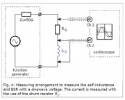
The following test arrangement was used, hoping to test the suitability of my 'cheap and dirty' dummy load.
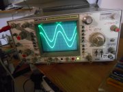
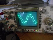
A 10 ohm resistor was used and the dummy load was tested from 20 Hz to 40 kHz. The scope traces did not shift in phase or amplitude through this frequency range. To 'test the test' the dummy load was replaced with a coil from a crossover network and run through the same tone sweep.
 

Attachments

Peter S

Journeyman
Joined
Jun 29, 2019
Messages
312
Location
Ontario Canada
No phase or amplitude change was noted between traces with the furnace element (upper pic), but some phase shift and tremendous amplitude change with the cross-over coil around the the 3 kHz point and above (lower pic).
 

Attachments

J!m

Veteran and General Yakker
Joined
Dec 24, 2019
Messages
10,708
Location
Connecticut
Tagline
BOT
Nice Clair............... I was thinking... since I like to be different, I wanted to mount a headlight switch for a power switch... Just pull the knob and rock out..... Or maybe a turn key ignition switch with a big ass skeleton key//////////////


HUH?
I like the ignition switch idea... Turn to start position to latch a contactor; something goes wrong and it drops power and the contactor drops out. Fail-safe (-ish)...
 

Peter S

Journeyman
Joined
Jun 29, 2019
Messages
312
Location
Ontario Canada
Just starting on the second Clair Bros amp. Perry was right about a new WO chassis saving some hassle. This Clair chassis required a minor elongation of the holes for the bias transistor, to line up with the holes in the back plane pcb's.
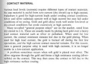
Anyway, so far so good! Just thought I would continue my tradition of being a ship-disturber and post this excerpt from Henry Ott's book. (Thanks again, Glen). This may support my personal bias against relay contacts in the audio path;
 

Attachments

Peter S

Journeyman
Joined
Jun 29, 2019
Messages
312
Location
Ontario Canada
Hi Folks;
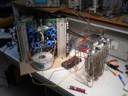
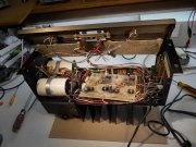
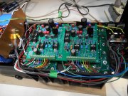
Hope you are all keeping well during these hectic times. I am making good progress on "The Second Phase". This PL700 II started out as a full complimentary. The second pic shows my AC wire routing; absolute shorted possible run from the IEC jack to the transformer. The wires to the power switch are shown in the upper left of the pic, routed further away from the left channel input IC.
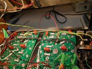
.......and yes I accidentally bent over a couple of the caps on the back planes but I'm not going to straighten them up until the patient is ready to be closed up for good (hopefully).
 

Attachments

Peter S

Journeyman
Joined
Jun 29, 2019
Messages
312
Location
Ontario Canada
PL14_20 rev G and the driver row of outputs installed. Hoping to install the rest of the outputs and do some testing today.
So, my 'harem' will consist of 2 Clair Bros WOPL's, a WOPL quasi PL700B, and an original PL700 still using all pl909's. Question; If I could Vbe match the pl909 outputs, would they be OK to use in a Peavey CS800 that I'm trying to restore 'on the cheap' and use as a backyard system?
 

Attachments

MarkWComer

Veteran and General Yakker
Joined
Nov 1, 2014
Messages
3,493
Location
Gaston, SC
Tagline
Victim of the record bug since age five
Question; If I could Vbe match the pl909 outputs, would they be OK to use in a Peavey CS800 that I'm trying to restore 'on the cheap' and use as a backyard system?
Funny thing... I was just thinking about a "backyard system" and thought about getting a reasonably inexpensive car radio/CD player and a car battery to power it, use my "beater" Magnavox 3-way speakers that I got for $12 from Goodwill. Something to use out at the fire pit...
 

WOPL Sniffer

Veteran and General Yakker
Joined
Aug 10, 2015
Messages
11,522
Location
Minnie-Soda
Tagline
Screw it
Hi Folks;
Hope you are all keeping well during these hectic times. I am making good progress on "The Second Phase". This PL700 II started out as a full complimentary. The second pic shows my AC wire routing; absolute shorted possible run from the IEC jack to the transformer. The wires to the power switch are shown in the upper left of the pic, routed further away from the left channel input IC.
.......and yes I accidentally bent over a couple of the caps on the back planes but I'm not going to straighten them up until the patient is ready to be closed up for good (hopefully).

I bend the caps over and leave them till the last possible minute. You'll never break one loose that way.
 

Peter S

Journeyman
Joined
Jun 29, 2019
Messages
312
Location
Ontario Canada
Thanks Perry, now I don't feel so bad! I was going to straighten them for the photo but I would probably just bump into them again before I button her up for good.
All the outputs are in, so I will try to test for power and noise before dinner.
 
Top