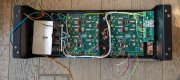
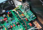
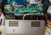
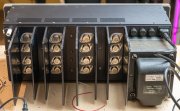
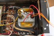
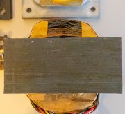
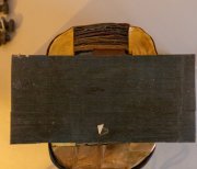
Before ordering the full Kit, I made some cleaning and finally checked the transformer. It looks like, but I may be wrong, that it had a little hot moment, if you look at the pictures. I tested it, looks like it's ok but without any load , and does not smell. Wondering what to do...
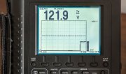
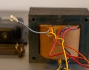
Btw, there is a grey wire not connected, should it be the midddle point of the 12V AC ? Output is 2 x 61V for 236V input
Btw, there is a grey wire not connected, should it be the midddle point of the 12V AC ? Output is 2 x 61V for 236V input


")


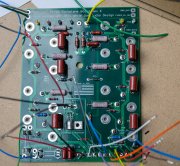
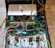
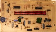
") . I just added a soft start circuit, and 2 foiled capacitors (belt and suspenders
. I just added a soft start circuit, and 2 foiled capacitors (belt and suspenders