PL 400 series 2 in progress before WOPL

Loggitie

New Around These Parts
Joined
Jan 24, 2024
Messages
18
#1
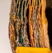
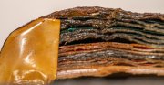
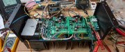
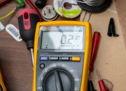
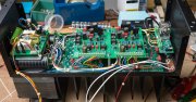
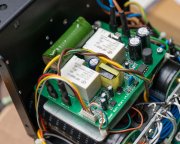
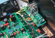
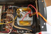
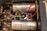
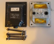
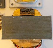
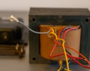
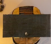
Before ordering the full Kit, I made some cleaning and finally checked the transformer. It looks like, but I may be wrong, that it had a little hot moment, if you look at the pictures. I tested it, looks like it's ok but without any load , and does not smell. Wondering what to do...
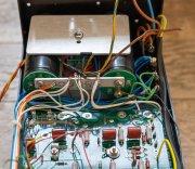
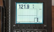
Btw, there is a grey wire not connected, should it be the midddle point of the 12V AC ? Output is 2 x 61V for 236V input
 

Attachments

mlucitt

Veteran and General Yakker
Joined
Jun 24, 2011
Messages
3,412
Location
Jacksonville, FL
#2
The unconnected Gray Wire is the Center Tap to the Lighting Circuit voltage of 2X6V, so that you can get 12V to the LED Light Bars. This Gray Wire is sealed at the factory and should be left alone. The transformer looks typical to me.
 
Joined
May 17, 2023
Messages
304
Location
Finland via the deep south
Tagline
Details, details
#4
Thank you for your comments. I am located near Luxemburg, Europe.
I was wondering about the "...236v input"...figured you were on this side of the pond. Welcome to the group, bunch of excellent resources here and the Godfather himself (or should I call him "Admiral"?) of all the fine WO products. I recently did a full WOPL on my 700B, sounds amazing.

Good luck with your build.
 

Loggitie

New Around These Parts
Joined
Jan 24, 2024
Messages
18
#5
The unconnected Gray Wire is the Center Tap to the Lighting Circuit voltage of 2X6V, so that you can get 12V to the LED Light Bars. This Gray Wire is sealed at the factory and should be left alone. The transformer looks typical to me.
Part of the secondary windings are blue instead of copper color :(
Z8R_2587.jpg Z8R_2589.jpg
 

George S.

Veteran and General Yakker
Joined
Feb 18, 2020
Messages
4,700
#7
I think it's good. In my photo are three spools of "copper magnet wire", used for making the windings of transformers, chokes, toroids, etc.
Notice I scraped the coating off the thick wire, with a razor blade.
The copper is under that thin, tough, coating, which provides insulation for the windings.
You can always test the output of the transformer if you have doubts.
Just know what your doing and proceed with caution as the voltage is lethal. If unsure how to test it, find someone local to show you.
 

Attachments

Loggitie

New Around These Parts
Joined
Jan 24, 2024
Messages
18
#8
I think it's good. In my photo are three spools of "copper magnet wire", used for making the windings of transformers, chokes, toroids, etc.
Notice I scraped the coating off the thick wire, with a razor blade.
The copper is under that thin, tough, coating, which provides insulation for the windings.
You can always test the output of the transformer if you have doubts.
Just know what your doing and proceed with caution as the voltage is lethal. If unsure how to test it, find someone local to show you.
OK, thank you very much to confort me ! I did test it, and it looks ok. I connected the 12V AC to VU meters, and it works fine. I will replace all capacitors on it, while waiting for the full kit. Here are some pictures of the dismantling : the Led VU meter board, the cooling set to be cleaned, the drivers board (one 40327 dead), and 3 PL909 dead also (2 different rows). So I still have 9 PL909 and the 4 drivers alive, one channel was working fine.
 

Attachments

George S.

Veteran and General Yakker
Joined
Feb 18, 2020
Messages
4,700
#9
Excellent. Your going to enjoy your WOAD WOPL kit. They're first rate and a joy to build.
I've built 2 400's and a 700 so far. They're fantastic amps.
Get a good workspace, light, tools, etc. Take your time and don't rush the build.
And, continue to ask any questions, the group will try their best to help.
 

Loggitie

New Around These Parts
Joined
Jan 24, 2024
Messages
18
#11
after several days laying in the EU customs, the full kit arrived at home.
I'm really impressed by the professionalism with which this kit has been organized. Everything is clear, the material is first-rate. My Stetson's off to Joe.
Now it's time to move on to the assembly of all these elements, to be continued...
 

Attachments

Loggitie

New Around These Parts
Joined
Jan 24, 2024
Messages
18
#13
The PL400 is alive and working :) . I just added a soft start circuit, and 2 foiled capacitors (belt and suspenders ;) ) to prevent any DC input (bad experience long time ago, using a preamp with a leaking trantalum capacitor ). DC at the outputs are 0.2mV right, 1.9mV left. Bias set at 320mV for the moment. Now it's time to order speakers, looking at 2 JBL 4312G, and a DAC. If you have other suggestions, you are welcome !
 

Attachments

mlucitt

Veteran and General Yakker
Joined
Jun 24, 2011
Messages
3,412
Location
Jacksonville, FL
#14
Where did you get the Soft Start circuit board? Most of us think the PL700B/PL700 II needs a soft start more than a PL400, others say no soft start is necessary at all. They point to thousands of Phase Linear amplifiers that have never had a bad start up.
 

Loggitie

New Around These Parts
Joined
Jan 24, 2024
Messages
18
#15
Where did you get the Soft Start circuit board? Most of us think the PL700B/PL700 II needs a soft start more than a PL400, others say no soft start is necessary at all. They point to thousands of Phase Linear amplifiers that have never had a bad start up.
It's coming from here : Power Soft Start v4 | Connex Electronic . It delivers also 12V DC 1 amp, and can be used for stand by as well. Maybe overdue for a 400, but i remember a 10A fast fuse blowing when i started my custom 700 after a long period of time (toroidal + 2x 19000µF). It is not so expensive, and looks vey well done for a chinese product.
 

wattsabundant

Chief Journeyman
Joined
Apr 26, 2011
Messages
878
Location
Central Ohio
#16
Where did you get the Soft Start circuit board? Most of us think the PL700B/PL700 II needs a soft start more than a PL400, others say no soft start is necessary at all. They point to thousands of Phase Linear amplifiers that have never had a bad start up.
The only need for soft start is to protect the power switch. The triac board I use for 700's easily handles the 120-150 amp inrush currents on the first cycle.

I wouldn't use a soft without an output relay. There's a stability/race condition that will damage speakers.
 

Artied2

New Around These Parts
Joined
May 31, 2017
Messages
21
Location
Jax, FL
Tagline
Jax, FL
#17
Beautiful work. I have a couple questions about the backplane:

Does it take the place of the TO-3 sockets? Do the transistors solder in direct, or do they still go into a socket of some sort?

Thanks;
Artie
 

George S.

Veteran and General Yakker
Joined
Feb 18, 2020
Messages
4,700
#18
No soldering the leads. The output transistor leads plug into gold plated contact cups that are soldered to the backplane circuit boards.
This is normal construction I've seen first hand on high amperage power supplies and active electronic load banks.
Only difference is Joe's parts and board kits have higher quality than anything I've seen commercially available. The kits are a bargain if you price all the components.
You won't be disappointed. I've built three full WOPL's. A 700 and two 400's.
 

Artied2

New Around These Parts
Joined
May 31, 2017
Messages
21
Location
Jax, FL
Tagline
Jax, FL
#19
Ah, cool. I get it now. I've seen those "turrets" before only in pictures. They look very similar to the little feed-through turrets that you'd use to repair an eyelet on a double-sided board.

The backplane board really makes it look like a "pro" job. (Not that you aren't.)

P.S. Do you solder those in, or are they a "press" fit?
 
Top