PL-400/1 “Linda” repair

AngrySailor

Veteran and General Yakker
Joined
Oct 15, 2014
Messages
3,419
Tagline
---not quite right
#1
Figured I’d put this in a new bread instead of the DCP/WO light board one.

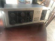
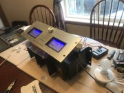
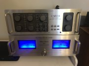
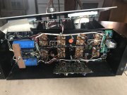
If you haven’t read the other thread, this amp is stock other than main caps and some repairs over the years. I installed a DCP board and a WO light board recently with no problems. I hooked it to a PL4000 pre amp which decided to randomly go full blast and toasted the 400.

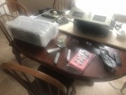
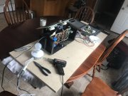
This is really my first dive into a repair like this so I’m sure there will be lots of questions! Here’s where I’m at...

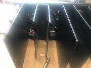
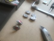
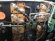
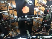
The left channel seems OK with my multimeter and has had its outputs replaced at some time with NEC2SD555’s and looks like the drivers have been changed also with one RCA 66546 and the other is Motorola MJ15015

The right channel has PL909 outputs which also look not original and has RCA 410 drivers. This channel has shorts.

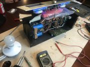
So far I’ve desoldered the emitter resistors on the bad channel and found two shorted outputs. One on each rail. I brought her up on the DBT and she failed, only on for a second but the meters swung full sweep. I then realized I had a brain fart and that those outputs were probably shorted to base as well, which they were... I desoldered them from base buss bar which then showed no shorts on the multimeter. I then powered her up on a DBT again and she came to life and the bulb dimmed normally. I hope I didn’t toast anything worse than she was...

I have outputs on the way with a package from grapplesaw which should arrive this week. Question is, what’s next? How can I test for other issues such as the driver board or any other collateral damage?
 

Attachments

laatsch55

Administrator,
Staff member
Joined
Jan 14, 2011
Messages
74,248
Location
Gillette, Wyo.
Tagline
Halfbiass...Electron Herder and Backass Woof
#2
No need to desolder emitter resistors or any other component on the backwall. Just pull the output and test.
Hang out and be groovy till your outputs show up. You may have gotten lucky.
RCA 410'S atebthe driver of choice. The 66456 atevrebranded 410's. The 15015 should be replaced with a 410.
 

laatsch55

Administrator,
Staff member
Joined
Jan 14, 2011
Messages
74,248
Location
Gillette, Wyo.
Tagline
Halfbiass...Electron Herder and Backass Woof
#3
You can check transistors on the board in circuit for shorts. Do the same for the bias transistors attached to the backwall. Use caution when manipulating the board and avoid flexing of the bias transistor leads as much as you can. They are brittle.
 

laatsch55

Administrator,
Staff member
Joined
Jan 14, 2011
Messages
74,248
Location
Gillette, Wyo.
Tagline
Halfbiass...Electron Herder and Backass Woof
#4
Your solder gun may be a little much for the small signal transistors on the board. You can kill em with too much heat.
 

AngrySailor

Veteran and General Yakker
Joined
Oct 15, 2014
Messages
3,419
Tagline
---not quite right
#5
Shoot, the outputs are socketed? The bias transistors are the two bolted to the back wall in the little heat sink? I have a small soldering iron for the finer work also.
 

laatsch55

Administrator,
Staff member
Joined
Jan 14, 2011
Messages
74,248
Location
Gillette, Wyo.
Tagline
Halfbiass...Electron Herder and Backass Woof
#6
Yes, the outputs are socketed...yes the bias transistors are mounted to the backwall by their P-strap..
 

AngrySailor

Veteran and General Yakker
Joined
Oct 15, 2014
Messages
3,419
Tagline
---not quite right
#8
My meter is acting quiffy, won’t zero but the bias resistors don’t seem to show any dead shorts. Checked across all terminals, reversed leads and got a lowest reading (if accurate) of 158 ohms one side and ~190 ohms the other. I’ll have another meter this evening.
 

laatsch55

Administrator,
Staff member
Joined
Jan 14, 2011
Messages
74,248
Location
Gillette, Wyo.
Tagline
Halfbiass...Electron Herder and Backass Woof
#9
You need a meter with a diode test function to test semiconductors effectively.
 

AngrySailor

Veteran and General Yakker
Joined
Oct 15, 2014
Messages
3,419
Tagline
---not quite right
#10
It has diode test, I’ll see if it’s working. Whole meter acting up. Don’t really trust it...
 

AngrySailor

Veteran and General Yakker
Joined
Oct 15, 2014
Messages
3,419
Tagline
---not quite right
#11
Bad channels outputs removed. I’ll resolder my oopsie on the backplane and I have another meter coming at rum o’clock which just happened to be in one hour.

I have the new outputs here. After soldering things back up, should I install them one row row at a time and DBT? I have new sil pads, they gonon dry right?
 

Attachments

mlucitt

Veteran and General Yakker
Joined
Jun 24, 2011
Messages
3,375
Location
Jacksonville, FL
#12
Yes, dry Silipads!

You can also test the bias transistors by measuring the bias voltage while on the dim bulb. Should be about 0.350 VDC. Best to use an accurate digital voltmeter. The bias measurement/adjustment is available, if you don't have it, here:

Bias Adjustment for a “stock” PL400 (from paragraph VI-5.a. of the Service Manual):
  1. Allow the unit to warm up sufficiently. Ideally the bias should be adjusted after the unit has achieved normal operating temperature.
  2. Remove all input and output connections to the amplifier. Locate R38 and R39 (10-ohm, 1/2-watt) in each output bank (R24 and R41 on units fitted with PL400C PCB).
  3. Measure the DC voltage drop [use alligator clips clipped onto the resistor while the amp is off] across R38 (R24 on PL400C units). Verify a reading of 300-400mv DC and adjust R20 in that channel on the PC board (R14 on PL400C) to obtain this reading. Once this measurement is obtained measure the DC voltage drop across R39 (R41 on PL400C units) and verify that it is within 20% of R38 (R24 on PL400C units).
NOTE: For amplifiers used in sound reinforcement or commercial use it is recommended that the bias be adjusted closer to 300mv across R38 (R47 [typo] on PL400C units). This will increase distortion only slightly, but more importantly will provide for much cooler operating temperatures. A cooling fan is still recommended, however.

Of course, measure and adjust both channels, using R38 and R39. The readings will drift with the heat in the amplifier, so we say 0.350-0.380 VDC is the target.

Good luck.
 

AngrySailor

Veteran and General Yakker
Joined
Oct 15, 2014
Messages
3,419
Tagline
---not quite right
#13
Thank you! Soldering the backplane rn. One column done. No biggie.
 

AngrySailor

Veteran and General Yakker
Joined
Oct 15, 2014
Messages
3,419
Tagline
---not quite right
#15
Passed DBT with the backplane resoldered, Installed one pair of outputs and seems like it failed. Light on but not hard on, I didn’t hear the DCP click, but I didn’t leave it on very long
 

AngrySailor

Veteran and General Yakker
Joined
Oct 15, 2014
Messages
3,419
Tagline
---not quite right
#16
These transistors probably require a different bias voltage? How should I proceed?
 

AngrySailor

Veteran and General Yakker
Joined
Oct 15, 2014
Messages
3,419
Tagline
---not quite right
#17
Bias was 590mV good channel, 1.2v bad channel with no outputs installed.
 
Top