Wheel-right
Chief Journeyman
Gotta pay for that Singer quality, American made. The projector is pretty cool too. Next WOPL install a Singer faceplate?Damn bro, I can buy 10 Close N Play's for that.....")

Gotta pay for that Singer quality, American made. The projector is pretty cool too. Next WOPL install a Singer faceplate?Damn bro, I can buy 10 Close N Play's for that.....
Do you still have that 3125?If one comes along under the right circumstances. I'am trying to do trades instead of buying, but my restored MCS 3125 isn't getting a lot of interest and I am happy to keep that beast for my shop system.
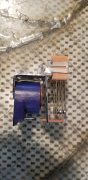
Pic of the relay?


Okay... order placed, grin.I know that relay, you are going to have a hard time replacing that.
Unless you look here:
https://tinyurl.com/3rsrpf62
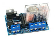
I did that before I knew about Watts Abundant and his most excellent DC Protect Relay/Delay Board. I even installed a small separate 12V transformer to power the Chinese speaker disconnector in my PL700B (the 6V lighting voltage was not high enough). It worked until the relay got stuck and then no more tunes...I'm gonna try one of these things from that 'Bay place. It's an add on to the back of 'any' amp, and remotely 12VAC powered.
I did that before I knew about Watts Abundant and his most excellent DC Protect Relay/Delay Board. I even installed a small separate 12V transformer to power the Chinese speaker disconnector in my PL700B (the 6V lighting voltage was not high enough). It worked until the relay got stuck and then no more tunes...
You get what you pay for.

How long should these relays last? Since I received the unit in a failed state and others have obviously worked on it, I have no idea if the part I found in there is correct. The installed one is an apparently unsuppresed coil designed to work on AC voltages, but is fed with a DC voltage of apporximately 50% of the coil rating through current limiting resistors on both legs. I may have measured that voltage with respect to the wrong reference point, but it still seemed strange to me.Like this..I've got a few..
I have no idea how long they last, and to how they are driven, I've never even looked at a schematic. have you actually measured DC voltage on the relay coil terminals?
Yes, the 55 VDC value I stated earlier was a measurement at the coil. The coil of mine measured as open circuit.I have no idea how long they last, and to how they are driven, I've never even looked at a schematic. have you actually measured DC voltage on the relay coil terminals?
.could I know the voltage that powers the LEDs in PL200 thanks EgidioNew member here. I need a bit of help, but first let me introduce myself. I found this forum via Audiokarma, where I have an account under the same handle. I've been a fan of vintage audio for years, ever since I picked up a Yamaha CR-2020 when I was in college 13 years ago. I've recently gotten the courage to do a little restoration work, motivated by the desire to get that Yamaha back to working order. After a complete re-cap, updating, and service on my Yamaha, I did the same for my other receiver, a Sony STR-7800SD. I thought having these two beasts was enough, but I've kept my eyes open for an opportunity to try separates, and that has lead me here. With the intro out of the way, on to the topic at hand:
I came across a Phase Linear 200 series 1 amp and 2000 pre, both with the wood cabinets. They came untested, but the price was right ($75 for the pair). I'd like to restore both units, but I'll start with the 200, since its the one with obvious issues. Up to this point, I've only worked on gear that still functioned, so I've not had a chance to play detective before, and I am hoping that with an amp as simple as the 200, the experts here can guide me to a fix.
Here is what I've found, and pictures are included for reference as well:
- The unit powered on with a DBT - all good so far.
- Plugged it in, relay clicked on.
- Went to measure DC offset and found an issues. Right channel measured 30mv at turn on, and went down to about 8mv after a few minutes. The Left channel however is at 750mv.
- voltage across filter cap while plugged in was ~70 volts.
- after about 10 minutes, the relay clicked and the unit went into protection. Plugging it back in about 20 minutes later, it came out of protection.
- The transformer has a bit of hum, which decreased when the unit went into protection.
- The PL19 23600 boards are not identical. Some of the components are different between the two boards. Not sure if this is normal.
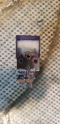
- There is a burned up transistor on the board that is mounted at the front of the unit (photo included). I am assuming this would not cause the high DC and protection, being on the front board.
I am not very knowledgeable about what to test or look for, so I am hoping someone can give me some ideas on what to check. Other than the bad resistor, I didn't find any obvious damage.
Front and Back:
View attachment 39852
View attachment 39848
Burned out resistor (its the one with the red shoulder in the middle of the photo):
View attachment 39853
PL19 cards:
View attachment 39849
View attachment 39850
View attachment 39854
I have a crappy copy of the schematic, but no service manual, so if anyone has a copy they can share, it would be very much appreciated. Thanks, and I am looking forward to working on this!
I was almost right. The LED circuits are fed by their own tap from the power transformer, via an (unfiltered!!!) full wave bridge constructed from discrete 1N4004 diodes on the high side (B2+), and the low side is connected to ground. The output voltage is not specified but we can do some homework:.could I know the voltage that powers the LEDs in PL200 thanks Egidio