PL 200 Help Please!

bobdod

New Around These Parts
Joined
Feb 18, 2020
Messages
23
#1
New member here. I need a bit of help, but first let me introduce myself. I found this forum via Audiokarma, where I have an account under the same handle. I've been a fan of vintage audio for years, ever since I picked up a Yamaha CR-2020 when I was in college 13 years ago. I've recently gotten the courage to do a little restoration work, motivated by the desire to get that Yamaha back to working order. After a complete re-cap, updating, and service on my Yamaha, I did the same for my other receiver, a Sony STR-7800SD. I thought having these two beasts was enough, but I've kept my eyes open for an opportunity to try separates, and that has lead me here. With the intro out of the way, on to the topic at hand:

I came across a Phase Linear 200 series 1 amp and 2000 pre, both with the wood cabinets. They came untested, but the price was right ($75 for the pair). I'd like to restore both units, but I'll start with the 200, since its the one with obvious issues. Up to this point, I've only worked on gear that still functioned, so I've not had a chance to play detective before, and I am hoping that with an amp as simple as the 200, the experts here can guide me to a fix.

Here is what I've found, and pictures are included for reference as well:
- The unit powered on with a DBT - all good so far.
- Plugged it in, relay clicked on.
- Went to measure DC offset and found an issues. Right channel measured 30mv at turn on, and went down to about 8mv after a few minutes. The Left channel however is at 750mv.
- voltage across filter cap while plugged in was ~70 volts.
- after about 10 minutes, the relay clicked and the unit went into protection. Plugging it back in about 20 minutes later, it came out of protection.
- The transformer has a bit of hum, which decreased when the unit went into protection.
- The PL19 23600 boards are not identical. Some of the components are different between the two boards. Not sure if this is normal.
- There is a burned up transistor on the board that is mounted at the front of the unit (photo included). I am assuming this would not cause the high DC and protection, being on the front board.

I am not very knowledgeable about what to test or look for, so I am hoping someone can give me some ideas on what to check. Other than the bad resistor, I didn't find any obvious damage.

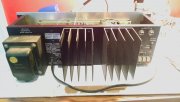
Front and Back:
IMG_20200218_142423002.jpg

IMG_20200218_142147297.jpg

Burned out resistor (its the one with the red shoulder in the middle of the photo):
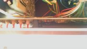
IMG_20200218_151858893.jpg

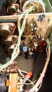
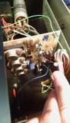
PL19 cards:

IMG_20200218_142247394.jpg
IMG_20200218_142320613.jpg

IMG_20200218_152554477_HDR.jpg

I have a crappy copy of the schematic, but no service manual, so if anyone has a copy they can share, it would be very much appreciated. Thanks, and I am looking forward to working on this!
 

Attachments

wattsabundant

Chief Journeyman
Joined
Apr 26, 2011
Messages
842
Location
Central Ohio
#2
Here is the manuals. See P20 of the 200 manual where it states the sereis II driver board replaced the 200 driver and the II was much more reliable. If you try to repair the 200 and keep the original circuit, extend the power cables so when it fails it's easier to repair.
 

Attachments

bobdod

New Around These Parts
Joined
Feb 18, 2020
Messages
23
#3
Here is the manuals. See P20 of the 200 manual where it states the sereis II driver board replaced the 200 driver and the II was much more reliable. If you try to repair the 200 and keep the original circuit, extend the power cables so when it fails it's easier to repair.
Thanks! much appreciated. It looks like the two service manuals you attached are identical documents, just better resolution on the one, right? They both show drawings for PL19 23512 cards, where my unit has PL19 23600 cards, but not sure if that means anything.

I'll try to go through some of the troubleshooting in the manual and see if anything comes up. Using the better resolution schematic, it looks like R34 is the damaged resistor shown in my original post.
 
Last edited:

bobdod

New Around These Parts
Joined
Feb 18, 2020
Messages
23
#4
More probing, now with the help of a service manual, revealed diode D4 on the left channel is shorted. Could this be the cause of the problems? Will any 1N4148 do as a replacement?
 

wattsabundant

Chief Journeyman
Joined
Apr 26, 2011
Messages
842
Location
Central Ohio
#5
I don't recall having seen that diode fail in any of the P/L amps. Anything is possible. 1N914 or 4148 will work there. R34 is a voltage divider to the display and if it's burnt it suggests a lot of DC on the ouptut. I wold suggest checking all semiconductors for shorts. No need to remove theme to check.
 

bobdod

New Around These Parts
Joined
Feb 18, 2020
Messages
23
#6
I don't recall having seen that diode fail in any of the P/L amps. Anything is possible. 1N914 or 4148 will work there. R34 is a voltage divider to the display and if it's burnt it suggests a lot of DC on the ouptut. I wold suggest checking all semiconductors for shorts. No need to remove theme to check.
The R34 resistor looked like toast (case is split and burned), so I assumed it was bad. Surprisingly it still checks out ok. I will obviously replace it. I've checked as many of the semiconductors as I could reach without disassembly and removal of the output transistors. I'll have to pull the outputs anyway to check them.

Any thoughts on what could be a possible culprit that would lead to R34 and D4 being out of sorts? could one have taken out the other, or is it likely there is another underlying issue? I don't know enough about reading schematics to put the dots together unfortunately.
 

wattsabundant

Chief Journeyman
Joined
Apr 26, 2011
Messages
842
Location
Central Ohio
#7
The shorted D4 diode would keep Q3 from turning on and allow Q7 to go full on which in turn drives Q8 & Q9 full on. The net result is the +DC power supply is fed to the output.

There is no reason to pull the outputs to check them. First touch the 2 meter leads together and if possible zero the meter. If you can't zero the meter (look for a "Rel" button) the reading you get will be considered zero ohms.

Read resistance from +Dc to the output and -Dc to the output. If it reads less than 1 ohm, read from collector to emitter of each transistor. The shorted device will be 0.1 ohm or so and the other one will read 0.4 ohms. This technique works and is documented in the 400 manual. Also see the troubleshooting section in the 200 manual.
 

nakdoc

Chief Journeyman
Joined
May 11, 2011
Messages
619
Location
Nashville, TN Music City
Tagline
highly biased
#8
A shorted D4 reduces the constant current to the class A driver, basically rendering the differential input pair incapable of controlling DC offset. Replacing it should take care of the offset. I doubt anything else is bad. R34 is only for the meter range. Odd that it would burn, so look for a stray wire touching something going to the meter range switch.
 

bobdod

New Around These Parts
Joined
Feb 18, 2020
Messages
23
#9
Don't have the diode on hand, so waiting on delivery. Will report back on results after replacement.
 

wattsabundant

Chief Journeyman
Joined
Apr 26, 2011
Messages
842
Location
Central Ohio
#10
A shorted D4 reduces the constant current to the class A driver, basically rendering the differential input pair incapable of controlling DC offset. Replacing it should take care of the offset. I doubt anything else is bad. R34 is only for the meter range. Odd that it would burn, so look for a stray wire touching something going to the meter range switch.
I think you answered your statement about the burnt R34. Yes, the diff amp could not control offset and I'm guessing the offset gradually rose until the protection circuit tripped. So a connected speaker would be spared, however the meter circuit is on the line side of the relay and therefor would continue to see whatever DC was on the output. R 34 is a voltage divider with the series parallel combination of R35-38 and a mess of voltage dividers for each LED. A rough calculation indicated the 1/2 watt R34 could have seen 3-4 watts which could make it smoke but not instantly burn up.

As for the shorted 1N4148 diode just about any diode including 1N400X types would allow troubleshooting to continue.
 

bobdod

New Around These Parts
Joined
Feb 18, 2020
Messages
23
#11
I replaced D4, and checked DC. It went up to 1250mv from 750mv. I then checked D5 and it was dead (it tested good when I checked it out yesterday). I replaced D5 and DC offset is now down to 240mv, but obviously the issue is not fully resolved yet. Any thoughts on what to look at next?
 
Last edited:

wattsabundant

Chief Journeyman
Joined
Apr 26, 2011
Messages
842
Location
Central Ohio
#12
The best thing would be to read pages 15-18 of the manual. Resist the temptation to do wholesale parts changes. Set the meter on the diode range and compare readings of Q1-3 in each channel with no power applied. Same for associated resistors. Once repaired there is still the issue of thermal runaway as noted in the manual.
 

bobdod

New Around These Parts
Joined
Feb 18, 2020
Messages
23
#13
I checked every diode, resistor, and transistor (in circuit). The only observed difference was with Q3. On the right channel (the good one) I got 682/675. On the Left Channel (the one with the high DC offset) I got 647/630. All others were pretty much the same in either channel.

I tried swapping the Q3's between the two boards. The result was a smokey R66, and death to D4 and D5 on the left channel again. I replaced the Q3's to their original boards and replaced the newly failed D4/D5, but the unit won't come out of protection, and R66 continued smoking. All components still test the same as before on both boards, except Q1 on the right channel is toast. The other observation after the Q3 swap is that the meter lights for the right channel are all on, and the meter lights for the left channel are all off. Prior to the Q3 swap, the left channel meter lights were all on and the right ones were off. I started pulling capacitors to test off of the left board and 2 out of the 3 electrolytics were bad, along with C22 (ceramic). I think the next step is to replace Q1/Q2/Q3, and all of the capacitors. Can anyone recommend substitutes for Q1/Q2 (both are MPSA93) and Q3 (2N3501)?
 
Last edited:

WOPL Sniffer

Veteran and General Yakker
Joined
Aug 10, 2015
Messages
11,223
Location
Minnie-Soda
Tagline
Screw it
#14
Those little transistors cannot handle the heat of you swapping them back and forth. Use the transistors as listed, they are available. As for wholesale replacing of parts, that's how you rebuild the boards... Do it. 40 year old parts is 40 year old parts.... Get rid of them.
 

bobdod

New Around These Parts
Joined
Feb 18, 2020
Messages
23
#16
I'am going to place the order for the transistors. Here is what I've found, let me know if anything looks problematic:
Q1/Q2 (MPSA93 existing) - https://www.mouser.com/ProductDetail/610-MPSA93
Q3 (40327/2N3501 existing, substituting with 2N3440) - https://www.mouser.com/ProductDetail/610-2N3440
Q4 (TIS97 existing, substituting with KSC1815YTA) - https://www.mouser.com/ProductDetail/512-KSC1815YTA
Q5 (TIS93 existing, substituting with 2N5401) - https://www.mouser.com/ProductDetail/610-2N5401
Q6 (IC13 existing, substituting with MJE15029G) - https://www.mouser.com/ProductDetail/863-MJE15029G
Q7 (IC12 existing, substituting with MJE15028G) - https://www.mouser.com/ProductDetail/863-MJE15028G

I chose the substitutions for Q4 - Q7 based on info I was able to find in other threads/forums since the originals are not available. For Q3, 2NS3501 can be purchased, but the 2N3440 is way cheaper, and based on this thread, is a good substitute.

Let me know your thoughts.
 

bobdod

New Around These Parts
Joined
Feb 18, 2020
Messages
23
#17
Bit of tinkering, and I am back to the unit staying out of protection, with DC offset reading 8mv on the right channel and 240mv on the left channel (so back to where I was after replacing D4 and D5). I replaced all of the electrolytics on the left channel, but didn't see any improvement even though 2 out of the three originals were no good. Still thinking I should try replacing Q1/Q2 to see if there is improvement.
 

laatsch55

Administrator,
Staff member
Joined
Jan 14, 2011
Messages
74,124
Location
Gillette, Wyo.
Tagline
Halfbiass...Electron Herder and Backass Woof
#18
That is where you will reduce offset if everything else is good. The closer Q1,Q2 are matched the lower the offset..
 
Top