VSAT88
Veteran and General Yakker
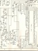
Knew some of those parts looked familiar. Some look like the same parts used on my PL 700 main board.Ugh!
Anyone seen this in a 700 series ll?
The led meter circuit is the same for both the 700 ll and dual500

Knew some of those parts looked familiar. Some look like the same parts used on my PL 700 main board.Ugh!
Anyone seen this in a 700 series ll?
The led meter circuit is the same for both the 700 ll and dual500