phase linear D 500 right channel LED not working correctly

Gepetto

Administrator
Staff member
Joined
May 15, 2011
Messages
13,944
Location
Sterling, MA
Tagline
Old 'Arn Enthusiast
#22
Ed will know. The meter boards have some third party manufacturer name on them so I think they were possibly done by an outside company and Phase Linear purchased the meter assemblies from them.
 

grapplesaw

Veteran and General Yakker
Joined
Aug 13, 2014
Messages
2,775
Location
Vancouver
Tagline
---
#23
Can not say who made the meter boards. I can tell you that 500 has a unique meter board. There are many additional things going on in it such as dc protection. High / low rail voltage control and various safety items

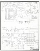
The circuit running the meters is basically the same and incorporated into the custom meter board. Attached is schematic of one channel meter section.
 

Attachments

Skywavebe

Chief Journeyman
Joined
Jun 13, 2010
Messages
725
Location
Bensenville, IL
Tagline
Work too much
#24
LED meter are just lighting as a result of the voltage being compared to a ladder of reference voltages and then fired as the voltage inceases to that level. I would look at the input to the meter board to see if abnormal levels or noise are there. If you disconnect the input then the meter should go down if it does not then there are shorted comparators or driver transistors in the chips. First when the unit is turned on I would make sure there would be no DC on the outputs but with correct DC detection by protection that would stop the relays from clicking. Just some things to check.
 

oldphaser

Chief Journeyman
Joined
Sep 8, 2012
Messages
848
#25
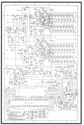
There are at least (2) versions of the PL33 meter drive board. One each for the Dual 500 and D-500. Likewise, there were (2) different owner's manuals (Dual 500 and D-500). The schematics in the back of these owner's manuals is different. The resolution of the scan is better in the owner's manuals than that of the Dual 500 service manual. The schematic in the Dual 500 service manual (revision B was drawn by Tom Nilson 6/21/78) is essentially the same as that of the one that is in the D-500 owner's manual . (In this thread its the same as Grappelsaw's partial scan of the schematic loaded on Dec 1, 2018). The schematic from the Dual 500 owner's manual was drawn by Desmond 2-1-77 and was more than likely the first revision (A).

I am not exactly sure who made the PL-33 PC board for Phase Linear. My best guess is Futronix since they made so many other pc boards for Phase Linear. Needless to say, Futronix is no longer in business. As a side note; the former Phase Linear employees who started Spectro Acoustics in eastern Washington were partners with the owner(s) of Futronix at one time.

I will double-check one of the several Dual 500/D-500's I am currently working on to see if the Futronix name or logo appears on the PL33 pc boards.

Phase Linear also did all the parts stuffing on the bare pc boards they purchased over the years that I am aware of.

(NOTE: Former Phase Linear employee Tom Nilson died in 2003 in Fort Worth Texas.)


Ed


Phase Linear D500 Owner's Manual schematic.jpeg Phase Linear Dual 500 Owner's Manual schematic.jpeg
 

oldphaser

Chief Journeyman
Joined
Sep 8, 2012
Messages
848
#26
I have been working on several Dual 500's lately. The PL-33 pc board was made by "SEIKO AAF". I have never heard of them previously. I did some searching on Google and saw another pc board made by them (for a computer) which said "made in the USA".

I will get to my D-500 a little later and see who the manufacturer of the PL-33 board is and see if it is someone different than SEIKO.

Ed
 

grapplesaw

Veteran and General Yakker
Joined
Aug 13, 2014
Messages
2,775
Location
Vancouver
Tagline
---
#28
Is this repaired or not. I repaired a 700 today with similar issue. I replaced the two uaa170 chips and the rc4558 chip All good mow
 
Top