Phase Linear 5000 Series 2

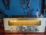
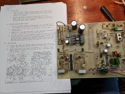
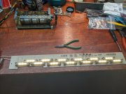
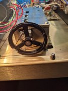
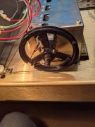
Well, I disassembled the 5000 S2 and the board is totally different from the service manuals that show the white dial S1. Good thing I took plenty of photos at each step of taking this apart.
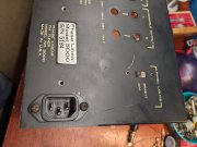
I've spent some time searching for the black dial S2 service manual and come up empty. I did see a S2 owners manual on eBay.
There are two RC4136DB opamps in the audio section that'll need to be replaced with Browndogs, and various film caps could be upgraded. Then what about the old carbon resistors? Really should upgrade to metal film.
Hmm, getting kind of burnt out on this. Think I'm going to step away from it awhile and try to find a S2 service manual.
 

Attachments

  • PXL_20211025_175701429.jpg
    PXL_20211025_175701429.jpg
    3.4 MB · Views: 10
Looks like the schematic for the S2 is in the owners manual, weird. Guess differences were so minor they never released a S2 service manual or maybe this is when they were bought by Pioneer. Just ordered the one listed on eBay. Also ordered Browndogs from Cimmaron Technology. May or may not get motivated to change all the resistors. Suppose it depends on the quality of the schematic. Ohming out old drifted carbon resistors is no fun.
 
Got the fuse bulbs, perfect fit. Marked AC 6.3V. On eBay they are shown as 6x41mm. 36 total LEDs on 13 lamps on the PL5000 lamp board. At 6 VAC they pull .75 amps and are blinding. The photo doesn't come close to showing the brightness. Tomorrow I'll do the math and calculate voltage dropping resistor values and figure out where to mount them, hopefully on the board replacing old components.
Received the PL5000 S2 Owners Manual showing the black dial tuner. Schematic that's included appears exactly the same as the S1 schematic, even though the boards layout is totally different. Weird.
 

Attachments

  • PXL_20211031_005820267.jpg
    PXL_20211031_005820267.jpg
    3.5 MB · Views: 9
  • PXL_20211031_010312810.jpg
    PXL_20211031_010312810.jpg
    3.5 MB · Views: 9
Got the IEC socket installed. I like to use pop rivets on the preamps, used screws here because the back panel is between the socket and chassis. Yup, those crusty screws are original PL.
 

Attachments

  • PXL_20211101_133003185.jpg
    PXL_20211101_133003185.jpg
    3.1 MB · Views: 15
Can anyone identify what this is? Found it loose inside the chassis.
 

Attachments

  • PXL_20211101_133636755.jpg
    PXL_20211101_133636755.jpg
    2.6 MB · Views: 20
  • PXL_20211101_133627700.jpg
    PXL_20211101_133627700.jpg
    2.6 MB · Views: 20
  • PXL_20211101_134018299.jpg
    PXL_20211101_134018299.jpg
    2.5 MB · Views: 20
Got the power supply rewired for proper polarity with the IEC plug. Unit had a non polarized cord, fuse was wired on one leg and switch on the other. Now neutral connects directly to the transformer. Line connects to fuse tip and from fuse base to switch, then back to transformer.
On off switch has dual contacts, but only one was being used. Jumped across them with a safety cap and now both sets are being used for longevity.
Been listening to Black Sabbath while I work.
 

Attachments

  • PXL_20211101_185538224.jpg
    PXL_20211101_185538224.jpg
    2.8 MB · Views: 12
Making progress. Used some Dale 5 ohm 50 watt 1% resistors to drop 12 VAC lamp board supply to appx 5.5 VAC. I pulled these out of a PL Pro 700 amp Zobel Network, and am happy I can reuse them. Way, way, overkill for this application, have heatsink compound on the mounting surface, I can't feel any heat at all, amazing. Now to calculate the dimming circuit resistor, thinking it will be approximately 50 ohms.
 

Attachments

  • PXL_20211108_004256591.jpg
    PXL_20211108_004256591.jpg
    3.1 MB · Views: 6
With 221 ohm 3 watt resistor bundle I have approximately 4.25 VAC and LEDs are dimmed nicely. The bundle is warm to the touch, so going to order a 250 ohm 5 or 10 watt power resistor and mount it on the back plate by the dimmer switch.
Unit is recapped, and the 19 MHz pilot capacitor is replaced. Tomorrow I'm going to reassemble it more, run through the test points, and try setting that pilot frequency with my HP counter.
 

Attachments

  • PXL_20211108_011725569.jpg
    PXL_20211108_011725569.jpg
    3.2 MB · Views: 5
Tuner alignment is an art unto itself i've heard...good luck George, we're pullin for ya!!
 
Thanks Lee. I really need a Stereo FM signal generator to do it right. The Boonton I have only does Mono FM. But, there are other options such as PC based.
At this point I'm just going to go over the voltage test points, set that FM pilot frequency, get it up and running. Then swap in the Browndogs and see how that goes.
Still looking for a good spectrum analyzer and the proper FM stereo generator, but no rush. I'll get back more in depth with these once I get the equipment, but lots of other things to do in the meantime.
Good thing is, it was a nice sounding tuner before I started, so alignment should be close enough for now.
 
Can anyone identify what this is? Found it loose inside the chassis.

Could it possibly be a partial 'pot' that has snapped off from the rest and missing the knob?
Maybe not necessarily belonging to this unit, but just check the back panel anyway.
If you unscrew the screw, does the remnants of a shaft fall out?
 
Last edited:
Could it possibly be a partial 'pot' that has snapped off from the rest and missing the knob?
Maybe not necessarily belonging to this unit, but just check the back panel anyway.
If you unscrew the screw, does the remnants of a shaft fall out?
Found it. Looks like it was originally designed as a "keeper" to keep the string wheel hub screws snug during shipping prior to assembly.
Looking at it further, at the glue residue on the bottom, and the shape of the pattern in the residue, it was then glued on the shaft. There is a perfectly matching rub mark on the cover from the screw.
Some gel super glue and it's back in place.
It must have fell off years ago as the tuning was a little loose because the shaft was partially out of the gear box.
 

Attachments

  • PXL_20211108_120655872.jpg
    PXL_20211108_120655872.jpg
    3.7 MB · Views: 8
  • PXL_20211108_121022442.jpg
    PXL_20211108_121022442.jpg
    3.5 MB · Views: 8
  • PXL_20211108_121459695.jpg
    PXL_20211108_121459695.jpg
    3 MB · Views: 8
  • PXL_20211108_121051604.jpg
    PXL_20211108_121051604.jpg
    5 MB · Views: 8
Last edited:
The lamp reflector is rusty on every unit someone has posted about on the web. This unit was no different. I hand sanded and wire brushed it. Most paint it, but I shot mine with Loctite clear Extend, then glued aluminum foil.
 

Attachments

  • PXL_20211108_152838493.jpg
    PXL_20211108_152838493.jpg
    3.7 MB · Views: 9
  • PXL_20211108_154825363.jpg
    PXL_20211108_154825363.jpg
    3.7 MB · Views: 9
Back
Top