Perfect. Makes for a more robust assembly. The spacing for the control board to fit may be off a little, but not much. Easily tweaked.how about this mr. george??

You are using an out of date browser. It may not display this or other websites correctly.
You should upgrade or use an alternative browser.
You should upgrade or use an alternative browser.
phase linear 400
- Thread starter gene french
- Start date
gene french
Veteran and General Yakker
- Joined
- Mar 6, 2022
- Messages
- 5,892
- Tagline
- music...the healer of souls...
thank you!!!Perfect. Makes for a more robust assembly. The spacing for the control board to fit may be off a little, but not much. Easily tweaked.
WOPL Sniffer
Veteran and General Yakker
gene french
Veteran and General Yakker
- Joined
- Mar 6, 2022
- Messages
- 5,892
- Tagline
- music...the healer of souls...
gene french
Veteran and General Yakker
- Joined
- Mar 6, 2022
- Messages
- 5,892
- Tagline
- music...the healer of souls...
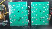
cleaned...leveled the nuts where mount to wall with sandpaper...chased the threads with a tap...cleaned...
WOPL Sniffer
Veteran and General Yakker
progress....taking my time...
Did you run a tap through the pems? It makes torqueing them correctly easier (don't forget to clean after the tapping). It also gets rid of the excess solder where you don't want it.
WOPL Sniffer
Veteran and General Yakker
cleaned...leveled the nuts where mount to wall with sandpaper...chased the threads with a tap...cleaned...
We think alike. We typed it at the same time
Great
gene french
Veteran and General Yakker
- Joined
- Mar 6, 2022
- Messages
- 5,892
- Tagline
- music...the healer of souls...
yes sir...i did...thank you!!!Did you run a tap through the pems? It makes torqueing them correctly easier (don't forget to clean after the tapping). It also gets rid of the excess solder where you don't want it.
gene french
Veteran and General Yakker
- Joined
- Mar 6, 2022
- Messages
- 5,892
- Tagline
- music...the healer of souls...
e30m3mon
Chief Journeyman
I found chasing those pesky threads made a huge difference when installing the outputs. Great techniqueyes sir...i did...thank you!!!
WOPL Sniffer
Veteran and General Yakker
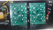
todays progress....
i have been super careful...taking my time...
double and triple checking...and of course cleaning...
Gene, if you go back to the first few pages of your thread, the improvement in your workmanship has improved immensely. Great work. You'll be the "Regional White Oak Rep" in no time. Taking one's time increases the quality of builds and THAT is a proven fact. Carry On
")
Vintage 700b
Chief Journeyman
Hello Gene,
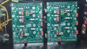
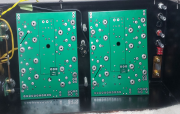
Excuse my format, but you may want to look closely at two of your sockets, and the one PEM nut that I have black lines pointing to.
It may be just the angle of the picture.
They look like they may cause an issue?
Excuse my format, but you may want to look closely at two of your sockets, and the one PEM nut that I have black lines pointing to.
It may be just the angle of the picture.
They look like they may cause an issue?
Attachments

gene french
Veteran and General Yakker
- Joined
- Mar 6, 2022
- Messages
- 5,892
- Tagline
- music...the healer of souls...
that means a lot coming from you mr. sniff!!!Gene, if you go back to the first few pages of your thread, the improvement in your workmanship has improved immensely. Great work. You'll be the "Regional White Oak Rep" in no time. Taking one's time increases the quality of builds and THAT is a proven fact. Carry On
thank you...very much for telling me!!!
gene french
Veteran and General Yakker
- Joined
- Mar 6, 2022
- Messages
- 5,892
- Tagline
- music...the healer of souls...
i have wore out 2 toothbrushes...lolDid you run a tap through the pems? It makes torqueing them correctly easier (don't forget to clean after the tapping). It also gets rid of the excess solder where you don't want it.
WOPL Sniffer
Veteran and General Yakker
i have wore out 2 toothbrushes...lol
Yep, I go through a lot of them along with a shitload of acid brushes. That reminds me, I need some more acid brushes. I wish I could find the same ones we had in the Navy supply system. Probably expensive as hell, but they didn't fall apart like these chinee ones.
gene french
Veteran and General Yakker
- Joined
- Mar 6, 2022
- Messages
- 5,892
- Tagline
- music...the healer of souls...
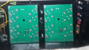
i had already found it...you can see in the last photo...it has been cleaned up....thank you for keeping your eyes on my work!!....Hello Gene,
Excuse my format, but you may want to look closely at two of your sockets, and the one PEM nut that I have black lines pointing to.
It may be just the angle of the picture.
They look like they may cause an issue?
all holes are clear and the cork stuff is still in the holes...
gene french
Veteran and General Yakker
- Joined
- Mar 6, 2022
- Messages
- 5,892
- Tagline
- music...the healer of souls...
Gene, if you go back to the first few pages of your thread, the improvement in your workmanship has improved immensely. Great work. You'll be the "Regional White Oak Rep" in no time. Taking one's time increases the quality of builds and THAT is a proven fact. Carry On
the bottom joint you pointed out is the solder joint on a cap...you got my curiosity up...i had to come check...lolololHello Gene,
Excuse my format, but you may want to look closely at two of your sockets, and the one PEM nut that I have black lines pointing to.
It may be just the angle of the picture.
They look like they may cause an issue?
Vintage 700b
Chief Journeyman
Hi Gene,the bottom joint you pointed out is the solder joint on a cap...you got my curiosity up...i had to come check...lololol
No, I meant the other end.....they are both sockets, Just did not want you to have an issue pushing your TO's home.
NIce job !!!
gene french
Veteran and General Yakker
- Joined
- Mar 6, 2022
- Messages
- 5,892
- Tagline
- music...the healer of souls...
must be tha angle..all is good!!!Hi Gene,
No, I meant the other end.....they are both sockets, Just did not want you to have an issue pushing your TO's home.
NIce job !!!
thank you so much for checking !!!
The pictures on how to do it are on the website Gene. The caps hide in the shadow of the bridge rectifier as Perry states.i put the writing up...never considered the reverse...
first of many...i am sure...