gene french
Veteran and General Yakker
- Joined
- Mar 6, 2022
- Messages
- 5,884
- Tagline
- music...the healer of souls...
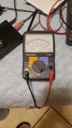
no...i use an analog voltmeterAre you using that AstroAI to check your transistors?

no...i use an analog voltmeterAre you using that AstroAI to check your transistors?
WHAT!!! Use the diode function on your AstroAIno...i use an analog voltmeter
GeneDon't mess around with the flyback diodes, they don't have anything to do with what you are chasing.
Take both driver transistors out of the right channel.
Take one of the left side drivers out, the one in the first column next to the transformer and move it to the 4th column.
You will now have a driver in column 2 and 4 starting from the transformer.
Put a GOOD PL909 transistor into column 1 and 3, bottom row.
Recheck your bias.
You only need the RCA410 or SJ2741 in column 2 and 4.
thank youyes sir...i will
Genethank you
I think that would be very slick and probably lower your blood pressure. I think you'd have a big smile every time you looked at it!i think that i am going to order a new chassis from joe for the new wopl....and build an 8 fin with the spare parts...
what u think??? george of the jungle????
yes sir....i am off to a late start this morning....did not sleep well....too much on my feeble mind...lolGene
Please post backplane pic w new config
When you bring power back up please post Voltages
I know this is Redundant ,
Report 1- DC Rail Voltages
2-Speaker protection Relay is On or Off
3- Dc offset w relay on, (Speaker output + to -) 3b- Relay off **** Measure before going into Relay board
Anybody else please add to list?
4. Update on what you did (your doing this already) but please add the Component # from Schematic
Thanks
Steve
dcprotect is out of circuit....i have the outputs disconnected....and am reading the voltages from the wiresGene
Please post backplane pic w new config
When you bring power back up please post Voltages
I know this is Redundant ,
Report 1- DC Rail Voltages
2-Speaker protection Relay is On or Off
3- Dc offset w relay on, (Speaker output + to -) 3b- Relay off **** Measure before going into Relay board
Anybody else please add to list?
4. Update on what you did (your doing this already) but please add the Component # from Schematic
Thanks
Steve
the bulk caps.yes sir....i am off to a late start this morning....did not sleep well....too much on my feeble mind...lol
i will document all....
where is the best place to read the rail voltages....since i cant do it from the outputs any more....lol...
i hate those things....lolthe bulk caps.


i hate those things....lol
from the plus on top cap to chassis ground and the minus on the bottom to chassis ground....
just want to be perfectly clear and make sure i am doing exactly as you ask...
i have moved the 2741s and installed the 909s....they are two different batches but all on each side are a matched set....the 909s i used as drivers will be matched to the outputs in each channel....
View attachment 66025
View attachment 66026
also....i am going to inspect the bias pots before i power up....
And put a PL909 in each location, not an XPL909i hate those things....lol
from the plus on top cap to chassis ground and the minus on the bottom to chassis ground....
just want to be perfectly clear and make sure i am doing exactly as you ask...
i have moved the 2741s and installed the 909s....they are two different batches but all on each side are a matched set....the 909s i used as drivers will be matched to the outputs in each channel....
View attachment 66025
View attachment 66026
also....i am going to inspect the bias pots before i power up....
ok....i will do that....And put a PL909 in each location, not an XPL909
thank you...ok....i will do that....
the xpl chips were original to this 400...and i no longer have a full set of those....for both channels...only one channel and one spare...
i replaced the one side that had bad outputs with the pl909s....i read they were interchangable...but unique per channel...
understood....i replaced the xpl with pl as instructed...They are, but you are debugging bias right now and would like to get to a place of similar behavior on each channel.