enoyes12
Journeyman
- Joined
- Feb 14, 2014
- Messages
- 171
- Location
- Phoenix, AZ
- Tagline
- No, I won't turn it down but you CAN go away!
Where are they PCB or case?


Picked up the test transistors at lunch today. Looking forward to popping them in and seeing if the bias adjusts.
Picked up the test transistors at lunch today. Looking forward to popping them in and seeing if the bias adjusts.
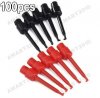
Do yourself a HUGE favour and pick some probes similar to these when taking measurements in confined areas, indispensable.
Mouser is showing 6 different 5088's. Which one am I looking for? Also whats the model number of the pots I'm looking for?