Phase Linear 2000 recap questions

A few questions about this rebuild- are you sure those coupling caps should be 22μF?
What about those mods on the opamps and circuit boards?
Please view, PLEASE comment!
 
The pin header is a convenient place to check rail voltage.
Hopefully Joe will comment about the output DC blocking caps.
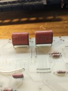
Think I'm using the largest Panasonic ECW value there, 6.8 uF if I remember correctly. Mark L. is using a much larger value there.
As for the typo on the cap value, I'll have to look at my Series 2 manuals and see what they have entered.
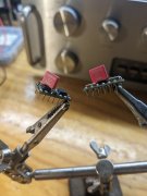
The small films on the Browndogs are bypass caps, added because PL neglected to add these to the original design. Best way to apply bypass caps is between the opamps power supply pin and ground, with very short leads. Unfortunately there are no nearby grounds. The second best way to apply bypass caps is between the opamps two power supply pins, as the photo shows. Keep the leads as short as possible.
Adding the opamp bypass caps slightly decreased overall distortion as seen by a QuantAsylum QA403 Audio Analyzer during before and after testing
The S2 has improvements over the S1. I have one S1 board, and have only given it a casual look over. The only differences that stood out were the 4 drilled holes to mount the switch board. On the S2, these holes are silkscreened, but not drilled.
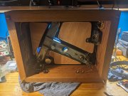
Working on my AR turntable and listening to The Allman Brothers.
 

Attachments

  • PXL_20231116_235225602.jpg
    PXL_20231116_235225602.jpg
    2.4 MB · Views: 18
George S.:
Thanks most profusely! And apologies- I attributed the photos from your build to Mark Lucitt by mistake.
Those bypass caps- small ones I’m sure- about .22μF or so?
That R/C combo mod shown on the circuit board still irks me, though. Factory schematic shows it, circuit board doesn’t have it.
 
Most use 0.1 uF films. Pure Polypropylene is best from what I've read. Others are using Multilayer Ceramic Capacitors (MLCC), most often a COG formulation, and mounting them on the backside of the board.
If you look at the photo you'll see small films with long leads. I used what I had on hand for this.
It would have been better to use wider caps with a lead spacing that closely matches the solder points to keep the leads as short as possible.
I've since purchased wider films and MLCC COG caps, but haven't gotten back to testing. Too busy enjoying retirement, and yes, it's great.
Maybe this winter I'll get back to the preamps.
 

Attachments

  • PXL_20231117_024504250.jpg
    PXL_20231117_024504250.jpg
    1.8 MB · Views: 25
And the S1 boards are different from the S2 boards. Traces are different. The board on the bottom is a S1 with a light underneath it. Compare the area the screwdriver is pointing to on the S2 board.
 

Attachments

  • PXL_20231117_031647277.jpg
    PXL_20231117_031647277.jpg
    2.3 MB · Views: 21
And, Panasonic ECW 4.7 uF Polypropylene films at the outputs.
Joe will have to elaborate on how higher values affect bass response. I don't understand it, but hopefully will someday. I do want to test frequency response with higher values. Someday.
It would be easy to do as the switch board PCB feeds the outputs. Would be easy to just pig tail caps between the switch board and RCA output jack for testing.
Notice that the rear speaker jacks have no output caps. Hmmm. Lots to investigate here.
 

Attachments

  • PXL_20231117_032650951.jpg
    PXL_20231117_032650951.jpg
    1.6 MB · Views: 12
This is what I used, the result was pure bliss and no loss of Bass:
PL2000 22uF 63VDC TDK Film Output Capacitors.jpg

The pin locations were almost perfect. The Mouser P/N for the 22uF 63VDC TDK Film Output Capacitors is: 871-B32523R226M. They are $4.49 each.


The Teflon insulated jumpers are shown on the underside of the circuit board:
PL2000 AC Wiring.jpg
 
And, Panasonic ECW 4.7 uF Polypropylene films at the outputs.
Joe will have to elaborate on how higher values affect bass response. I don't understand it, but hopefully will someday. I do want to test frequency response with higher values. Someday.
It would be easy to do as the switch board PCB feeds the outputs. Would be easy to just pig tail caps between the switch board and RCA output jack for testing.
Notice that the rear speaker jacks have no output caps. Hmmm. Lots to investigate here.
the 4.7uF that George has installed when coupled with the input impedance of the WOA PL14-20G1 board (~49K) has a -3dB point at 0.7Hz and therefore is essentially flat down to 2.8Hz. If you are driving into a lower input impedance, that frequency will move upwards from 2.8Hz. The original value used by PL was 1.1uF (2x2.2uF in series) which moves that 2.8Hz up to 12 Hz. Bigger is better...
 
Mark C., note Mark L's voltage dropping resistors between the transformer and the board. This drops the rail voltage to a acceptable level for the opamps when using the original transformer with today's higher wall voltage.
Also note the bypass caps he's added parallel to each rectifier diode. This reduces noise, and is pretty much standard. PL cut costs by leaving them out
 
And those Panasonics are a good choice in that location.

I used them in my headphone amp and that thing sounds amazing... cheap too!
 
Mark C., note Mark L's voltage dropping resistors between the transformer and the board. This drops the rail voltage to a acceptable level for the opamps when using the original transformer with today's higher wall voltage.
Also note the bypass caps he's added parallel to each rectifier diode. This reduces noise, and is pretty much standard. PL cut costs by leaving them out
Power supply application, should I use anything higher than a 3watt resistor?
 
And those Panasonics are a good choice in that location.
No one wants a turn ON or turn OFF “thump”. You may want to install a 4.7M Ohm 1/4W 1% resistor, or something close to that, from those larger value Capacitors to Ground to ensure they bleed off properly when powered down.
 
Back
Top