NEW PREAMP DESIGN

GeorgeP

Journeyman
Joined
Mar 22, 2023
Messages
107
#21
Jim,
Did you use hot air for soldering the SMDs? If so, which hot air gun do you have. I am looking at a few.
No Hot air here. I use a very very fine tip iron. Procedure for caps and resistors:
1. Put small amount of solder on one pad
2. With part in tweezers, heat pad while sliding part onto the pad. Quickly remove iron. Make it straight centered the first time, being very careful.
3. Let it Cool.
4. Just heat other pad, quickly adding small amount of solder to flow that. one or two seconds of heat does it.
 

GeorgeP

Journeyman
Joined
Mar 22, 2023
Messages
107
#22
ILL UPLOAD A .PDF LATER. ITS ON ORDAD, in process.
I made a few corrections. Attached is the .pdf
I kept it simple, based on the original PL2000, but with much higher performance OP-AMPs, Better Film Caps, RF immunity, and minimal switches.
I upgraded my original PL2000 with chips, made a few changes and its super clean sounding with the 1602 chips. What a difference! This one will use the 1612s...even lower distortion and wider response. Look at that data sheet attached. It really is an amazing chip, and full environmental temp range. I don't think there is a better chip out there. The Original chips in the 2000, were 4136....just a compensated version of the first 741 chip.
When complete, I may decide to sell the product as kit if I can get 10 or more brave people interested, to get the price of the PCB and parts down.
 

Attachments

wattsabundant

Chief Journeyman
Joined
Apr 26, 2011
Messages
933
Location
Central Ohio
#23
Am I missing something? The schematic for the main output shows the wiper of a 50K pot feeding the output. The P/L 2000 uses an opamp as a buffer betweeen the pot and the output. Depending on the input impedance of the amp and the setting of the pot there will be some phase shift and effect on frequency response. Was the buffer stage intentionally deleted? I'm guessing the I/O chokes are RF beads.
 

GeorgeP

Journeyman
Joined
Mar 22, 2023
Messages
107
#24
Am I missing something? The schematic for the main output shows the wiper of a 50K pot feeding the output. The P/L 2000 uses an opamp as a buffer betweeen the pot and the output. Depending on the input impedance of the amp and the setting of the pot there will be some phase shift and effect on frequency response. Was the buffer stage intentionally deleted? I'm guessing the I/O chokes are RF beads.
Have another look, Its the same. The last stage is the tone control/buffer stage. Yes, RF filter to keep >1MHz signals out. I'll initially test for full bandwidth first, then install the filter... and test again.
 

J!m

Veteran and General Yakker
Joined
Dec 24, 2019
Messages
10,831
Location
Connecticut
Tagline
BOT
#25
No Hot air here. I use a very very fine tip iron. Procedure for caps and resistors:
1. Put small amount of solder on one pad
2. With part in tweezers, heat pad while sliding part onto the pad. Quickly remove iron. Make it straight centered the first time, being very careful.
3. Let it Cool.
4. Just heat other pad, quickly adding small amount of solder to flow that. one or two seconds of heat does it.
That’s how I started doing it but once I went to paste flux I never looked back.
 

J!m

Veteran and General Yakker
Joined
Dec 24, 2019
Messages
10,831
Location
Connecticut
Tagline
BOT
#27
I’ve seen that too but try flux on the board then set the chip. Heat each pad and touch your solder. It’s like magic.

Assuming it’s a nice or new board with good solder mask.

Check for bridges with 10X.
 

Mohawk

Chief Journeyman
Joined
Oct 29, 2019
Messages
722
Location
Ontario Canada
#28
No, plain iron. The flux is the key.
Agreed!

The use of the right amount of flux is key.
A couple of months back my son and I built a pair of nixi tube clocks that were loaded with smd parts and IC's..

Scary indeed until you get your method figured out.

I found my biggest stresser was trying to make sure every component was straight, as in 100% parallel to the next component or the edge of the board !

If you don't already have obsessive compulsive disorder building with SMD stuff will be your test !!!

Cheers!
 

J!m

Veteran and General Yakker
Joined
Dec 24, 2019
Messages
10,831
Location
Connecticut
Tagline
BOT
#29
Then you use a straightedge to keep them aligned…

I prefer through hole but most decent op amps only come in SMD packages. I attached them to adapter boards along with pins and attached the assembly to the main board.

The main board had pads for the SMD as well as pin holes but I figured if I screwed up I wouldn’t ruin the main board.

Doing it again I’d go straight to the main board.
 

wattsabundant

Chief Journeyman
Joined
Apr 26, 2011
Messages
933
Location
Central Ohio
#30
Attached is the original schematic along with the new version for comparison. It appears to me that the new version has what I assume to be the volume control (R30B) after the buffer and therefore in series with the output. It's entirely possible I'm wrong. If so kinfdly point out my error.
 

Attachments

GeorgeP

Journeyman
Joined
Mar 22, 2023
Messages
107
#31
Oh...I understand what you mean. I placed the volume controls at the output and no balance control. The gain stages are same. I am moving the volume controls back to the input side. No balance pot. Keeping the output source impedance low, is the better way to drive the power amplifier. An easy rework on the protoype. The better reason is that there is no chance to overdrive the input to the op-amps, with volume control backed off. I saw that play out today when I got the whole thing up and running.
BTW...those new op-amps are working very nice...no issues there!! I'll take data for the phono preamp stage RIAA curve. Both channels tracking EXACTLY the same, as are the tone controls. I did lose a filmchip cap...super quick soldering needed...or it melts and gets mushy...gone. Good thing I got a few spares ! They were not cheap!
Total power consumption...only 1.6 watts. Tranformer good to 6 watts. +/- 15v rails.. getting 10V RMS at clipping at the output. So far...so gooood!
also...its flat down to 5 Hertz to up over 35KHz...no RF filter to start. Should be thunderous! 20231014_200257.jpg
 

Attachments

Last edited:

GeorgeP

Journeyman
Joined
Mar 22, 2023
Messages
107
#32
Update on the New Preamp. I took some data on the preamp with all components installed. Very Clean signals. Some data attached below.
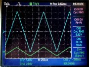
I will add a "gain tweak Adjustment" to Match the channels dead nuts. The tone controls work nice and both channels match and perform the same as the original PL2000. The frequency response is much better, and appears to be distortion less. Square wave and triangle waves look perfect.
For the next PCB REV P2, I am adding a "turn-on Mute" to avoid any turn on noises during turn-on and turn-off, using sealed relays. Also adding a LED level output indicator for each channel, with 3dB increments, 10 LED Bar graph display for 30 dB indications. Top RED Led will be a clip indicator just under full output.
I have a nice steel chassis to house the unit, so no external HUM issues. In was NOT able to detect any hum at all on the output signal with the high gain Phono section engaged. I'll be testing the RIAA response curve compliancy of the phono section in a week or so. The RF filtering on the inputs and outputs break in at 3 MHz, to avoid Amateur Radio, and other services getting into the 35 MHz op amps used in this preamp. I was able to see the local AM Radio station at the output at low level, so I'll check that when the steel chassis covers the circuits.
Attached are the schematics so far...still in process. Still need to add the Turn on Mute relay circuit to the schematic, and ref designations to the new PCB add-on PCB layout. Sinewave.jpg Triangle wave Test.jpg Testing  and New Knobs.jpg
 

Attachments

Last edited:

GeorgeP

Journeyman
Joined
Mar 22, 2023
Messages
107
#34
Are these for sale? I’d like to do a kit!
It will be a kit, to start. If its received well, I gat a bunch of boards populated. I just need to verify the P2 Rev PCB. It will have an option for SMT or Thru-hole for the Poly caps. Even careful hand soldering them can easily damage them as I found out. So, the next version I'll use the thru holes for those caps. DigiKey has thousands of each of those, but they are considered "NOT FOR NEW DESIGN" because they will stop production on them. due to surface mount demand is higher for the same values.
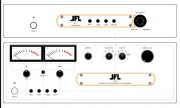
The bare board will require the kit builder to separate the 4 boards, as I'm having them made as one file to keep the cost down, I get 4 boards for the price of one that way. There will be hole perforations to cut them apart. you can see that on the board attachment for the main and rear panel PCBs. The connectors will connect the two, as well as the LED display PCB that will be separat, mounted in the side wall, and LED Bargraph PCB on each side of the front panel. Should look Coool. The chassis I chose is Black Steel, with the Silver knobs that you see.

Note: I have two REV P1 PCBs that I will not populate, to spend time on the new Rev-2 Pcb. If anyone wants them. $150 for each blank PCB just to recover initial prototype cost. , a few cuts and jumper wires are needed. I'll include the corrections, Excel parts list and schematic of course If not... the new one will be ready in 90 days or so.
 

MarkWComer

Veteran and General Yakker
Joined
Nov 1, 2014
Messages
3,505
Location
Gaston, SC
Tagline
Victim of the record bug since age five
#35
It will be a kit, to start. If its received well, I gat a bunch of boards populated. I just need to verify the P2 Rev PCB. It will have an option for SMT or Thru-hole for the Poly caps. Even careful hand soldering them can easily damage them as I found out. So, the next version I'll use the thru holes for those caps. DigiKey has thousands of each of those, but they are considered "NOT FOR NEW DESIGN" because they will stop production on them. due to surface mount demand is higher for the same values.
The bare board will require the kit builder to separate the 4 boards, as I'm having them made as one file to keep the cost down, I get 4 boards for the price of one that way. There will be hole perforations to cut them apart. you can see that on the board attachment for the main and rear panel PCBs. The connectors will connect the two, as well as the LED display PCB that will be separat, mounted in the side wall, and LED Bargraph PCB on each side of the front panel. Should look Coool. The chassis I chose is Black Steel, with the Silver knobs that you see.

Note: I have two REV P1 PCBs that I will not populate, to spend time on the new Rev-2 Pcb. If anyone wants them. $150 for each blank PCB just to recover initial prototype cost. , a few cuts and jumper wires are needed. I'll include the corrections, Excel parts list and schematic of course If not... the new one will be ready in 90 days or so.
Looking forward to this!
 

GeorgeP

Journeyman
Joined
Mar 22, 2023
Messages
107
#36
ANOTHER UPDATE:
I added the LED indicators for each channel, and a 3 second MUTE-DELAY. The op-amps had a 1 second set-up undefined as power supply regulators came up. The circuit is a 3 second "SHORT TO GND" at the output of all 4 Line outputs at turn on. I'm tweaking it for being faster at turn off of the AC. Similar to the Hafler design, but NO FETs for the control...they can be "non-linear" and are suseptible to failure. Relays are small sealed units.
So... look at the Curves! The RIAA curve is matched dead nuts even at the Line output. The Simulation is from 1 Hz to 30 KHz. The Line IN to Line Out is Flat as a
pancake. The RIAA Reference curve is there for reference. Prototype Breadboards Tested.jpg
I Hope to have the Final design ready soon, and order the New Rev-P2 PCBs with all the fixes in. I'll do a listen to this thing in a few days.
 

Attachments

GeorgeP

Journeyman
Joined
Mar 22, 2023
Messages
107
#38
Now...I see a transient with the AC power on. Easy fix, just a snubber across the AC switch terminals. A very narrow spike in the line out....Now Gone. Nobody want to rear any snap on turn-on! Lol...
 

MarkWComer

Veteran and General Yakker
Joined
Nov 1, 2014
Messages
3,505
Location
Gaston, SC
Tagline
Victim of the record bug since age five
#39
Just a stray thought now that you’ve gotten this far- will there be a headphone jack when the project is finalized?
 
Top