NEW PREAMP DESIGN

GeorgeP

Journeyman
Joined
Mar 22, 2023
Messages
106
#1
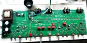
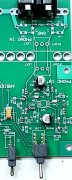
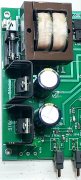
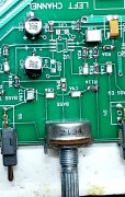
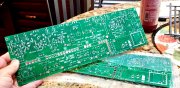
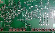
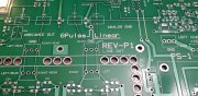
I just received the first PCB today.
This...should be the lowest distortion, lowest noise preamp at any price! THE BEST AND LATEST OP-AMPS, LAYOUT AND SIMPLE TO BUILD AND REPAIR.
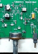
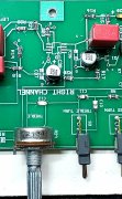
The latest Lowest distortion, lowest noise op-amps available. Film caps in signal path, Regulators, careful grounding, separate tone controls and turnover frequencies for each channel. And... the phase linear Ambience output cicuit for rear channels just to add something special. No digital processing!
WILL START PUTTING PARTS ON IT THIS WEEKEND. Will build power supply and regulstors first, and test it.
Then all passive parts installed. The last parts installed, the 4 super op-amps. That way...no chance of static damage.
Then...full bench testing. Stay tuned...
20230929_172914.jpg
 

Attachments

Last edited:

J!m

Veteran and General Yakker
Joined
Dec 24, 2019
Messages
10,376
Location
Connecticut
Tagline
BOT
#2
I’m tuned!

I hope @wynpalmer will stop in at some point. He designed op amps in his former life and knows a thing or two about them. His work on the phono preamp speaks for itself.

I was trying to get him to bring his knowledge and experience to bear on my concept but he decided to stop pursuing it. There was nothing unique about my concept but bringing ideas I like into one package- sort of like what you have done with the ambience circuit.

I specified analogue VU meters for each channel, level trim for each input (for matching) and of course a tape loop.

I posted PDFs of the faceplate design but I’d have to dig those out because it was about a year ago he and I were talking about it.
 

wattsabundant

Chief Journeyman
Joined
Apr 26, 2011
Messages
908
Location
Central Ohio
#3
What's with all of the fat holes? They're to big for any IDC (Insulation Displacement Connector) I can think of. Using sockets for opamps? Is there a ground plane? Clad made in Asia?
 

GeorgeP

Journeyman
Joined
Mar 22, 2023
Messages
106
#4
What's with all of the fat holes? They're to big for any IDC (Insulation Displacement Connector) I can think of. Using sockets for opamps? Is there a ground plane? Clad made in Asia?
The chassis is being defined, The huge holes will be easier to cut the board into two pieces...with the connectors then mounted on the back wall...then use wires with the 3 prong molex connectors you see on both sides of the streatch of big holes. Just an option to separate at that point...just in case...mostly mechanical. Ill test it attached first.
GOOD QUESTION!!
I get two prototype boards for the price of one to get started.
 

GeorgeP

Journeyman
Joined
Mar 22, 2023
Messages
106
#5
I’m tuned!

I hope @wynpalmer will stop in at some point. He designed op amps in his former life and knows a thing or two about them. His work on the phono preamp speaks for itself.

I was trying to get him to bring his knowledge and experience to bear on my concept but he decided to stop pursuing it. There was nothing unique about my concept but bringing ideas I like into one package- sort of like what you have done with the ambience circuit.

I specified analogue VU meters for each channel, level trim for each input (for matching) and of course a tape loop.

I posted PDFs of the faceplate design but I’d have to dig those out because it was about a year ago he and I were talking about it.
I may add peak reading LED BAR types. Good idea to meter the output of a preamp. Thanks for the idea...
 

J!m

Veteran and General Yakker
Joined
Dec 24, 2019
Messages
10,376
Location
Connecticut
Tagline
BOT
#6
I prefer bouncing needles. Found some on Amazon that I designed around for mine.
 

grapplesaw

Veteran and General Yakker
Joined
Aug 13, 2014
Messages
2,775
Location
Vancouver
Tagline
---
#7
Hi George
I always like to see something new
can you give a bit of detail on what the preamp is capable of. Number of channels output max voltage and the phono section details.
if we can give you support in any way we’ll be there. I may like to build one as well
Glen
 

J!m

Veteran and General Yakker
Joined
Dec 24, 2019
Messages
10,376
Location
Connecticut
Tagline
BOT
#8
Normally the circuit is two channels and the selection of source and/or tape loops are external to that.

So it could have 37 inputs if you wanted.
 

GeorgeP

Journeyman
Joined
Mar 22, 2023
Messages
106
#9
Hi George
I always like to see something new
can you give a bit of detail on what the preamp is capable of. Number of channels output max voltage and the phono section details.
if we can give you support in any way we’ll be there. I may like to build one as well
Glen
I just got the bipolar supplies up. maybe finish and test a week or so. Just Two Inputs, Phono and Line. I didn't want additional switches in the signal path. source switching add-on...external if wanted. I hate noisy switches. I'll post the progress.
 

GeorgeP

Journeyman
Joined
Mar 22, 2023
Messages
106
#11
I just got the bipolar supplies up. maybe finish and test a week or so. Just Two Inputs, Phono and Line. I didn't want additional switches in the signal path. source switching add-on...external if wanted. I hate noisy switches. I'll post the progress.
Added more parts. Ordered more parts.
I have an Excel spread sheet for all parts. I found a few minor errors in footprints, all usable. Ill install the super wideband no distortion chips last.
Parts arrive in 6 days or so...
I just got the bipolar supplies up. maybe finish and test a week or so. Just Two Inputs, Phono and Line. I didn't want additional switches in the signal path. source switching add-on...external if wanted. I hate noisy switches. I'll post the progress.
I just installed almost all SMT parts...More will arrive in a few days. Will install super wide-band no distortion chips last.
A few footprint errors, all usable for first turnon and measurements. Expected to do in a week or so. Wish me luck! 20231004_091254.jpg
 

Attachments

Magneto

New Around These Parts
Joined
Sep 30, 2023
Messages
13
#12
How about a schematic of this mystery preamp? You can leave off the component values. I'd just like to see the topology.
 

J!m

Veteran and General Yakker
Joined
Dec 24, 2019
Messages
10,376
Location
Connecticut
Tagline
BOT
#18
I didn’t like SMD at first but once you get a system down with a paste flux bath for the area you set the chip and flow a pad. Then another. The op amps often can be done four pins at a time.

Scary at first but not bad once you get the tricks down, and my tricks may not work for you- always a learning curve.

There can be advantages such as shorter runs as compared to wire leads but for our stuff probably fine either way.
 
Top