Need some help with my WOPL

Paul Haaskjold

New Around These Parts
Joined
Dec 16, 2022
Messages
9
#1
Hi guys, could use some help here. Doing a full WOPL with original chassi and Watts dcp board.
I got to step 38. in the bring up procedure, and got 11vdc on left channel output. :confused:

What to do?

I took out the two last transistors I installed on the left channel and still 10 - 11vdc.

Paul the Norwegain noob
 

Attachments

mlucitt

Veteran and General Yakker
Joined
Jun 24, 2011
Messages
3,469
Location
Jacksonville, FL
#3
Paul,
You might eliminate half of the possible components if your Left Speaker DC voltage is positive or negative. You did not specify.
Did any of the Backplane Boards fuses open?
Where did you find the washer? If it was between the Left Channel Backplane Board and the Chassis...
If the Speaker DC voltage is positive, I would check for shorted output transistors in the first column (looking inside). If the Speaker DC voltage is negative, I would check for shorted output transistors in the second column.

On the Control Board I would check the NPN Pre-Driver Q6L if the Left Speaker DC voltage is positive. If the Left Speaker DC voltage is negative, then check the PNP Pre-Driver Q9L.

You may find it easier to remove all the output transistors in the Left channel, you may find a bad one faster this way.

What is the Bias reading on the Left channel? You may have to replace the Left channel Bias Transistor.

Good Luck,

Mark
 

Paul Haaskjold

New Around These Parts
Joined
Dec 16, 2022
Messages
9
#4
Thanks Mark,
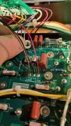
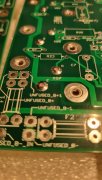
F2 fuse blown, I found it where the picture shows, between c11 and pad 12, not sure if it shorted these or not.
But it could have moved around some, my guess is it slid around some on top of the left backplane.

I pulled all 8 left channel transistors out and ohmed them (I don't know how to find a bad transistor)
all 195G are 155 - 165 kohm
two 196G are 170 kohm one is 110 and one is 120. (two bad ones?)

How to test Q6L and Q9L? can they be tested mounted to the board?

I put back the bottom two transistors, variac and dbt:
72vdc + to output, Bias .136.
(blown fuse not replaced for this test)

Paul
 
Last edited:

mlucitt

Veteran and General Yakker
Joined
Jun 24, 2011
Messages
3,469
Location
Jacksonville, FL
#5
Paul,
I would replace the Negative Rail F2 fuse, it clearly blew when the rogue washer shorted something. Your voltages will not be correct with F2 missing in action.
Then if the Bias cannot be adjusted, you will know the Bias transistor will have to be replaced.

Here is a little secret - the Phase Linear amplifiers use current sharing technology. The amplifier will work if any or all of the Output Transistors are faulty (not conducting), it just will not be capable of much volume because only the Driver Transistors are amplifying. However, if an Output Transistor is shorted B->C or E->C then the amplifier will blow rail fuses and not work at all. I think your Output Transistors are OK.

If the rogue washer shorted a path to Ground that was LEADING to the Output Transistors supply rail, then the maximum current will flow TO that point. That current path likely included F2 on the Backplane Board and D52L, Q51L, VR51L, and maybe more. I would like to know if you have -15VDC at the Test Point on the Control Board.

To check Q6L and Q9L on the Control Board, use the Resistance setting on your meter and compare across leg measurements to (known good) Q6R and Q9R. Treat those transistor legs as a pair of diodes, switching the polarity of your leads. I make a chart when I have to test these:

+Probe...-Probe......Q6L Value......Q6R Value......Q9L Value......Q9R Value
B...................C
C...................B
B...................E
E...................B
C...................E
E...................C

________ TO-220AB (the tab is also the Collector)
| __O__ | MJE150 Series
|.............|
|_______|
...| . | . |
...|...|....|
..B C...E
 
Last edited:

Paul Haaskjold

New Around These Parts
Joined
Dec 16, 2022
Messages
9
#6
Paul,
I would replace the Negative Rail F2 fuse, it clearly blew when the rogue washer shorted something. Your voltages will not be correct with F2 missing in action.
Then if the Bias cannot be adjusted, you will know the Bias transistor will have to be replaced.

Here is a little secret - the Phase Linear amplifiers use current sharing technology. The amplifier will work if any or all of the Output Transistors are faulty (not conducting), it just will not be capable of much volume because only the Driver Transistors are amplifying. However, if an Output Transistor is shorted B->C or E->C then the amplifier will blow rail fuses and not work at all. I think your Output Transistors are OK.

If the rogue washer shorted a path to Ground that was LEADING to the Output Transistors supply rail, then the maximum current will flow TO that point. That current path likely included F2 on the Backplane Board and D52L, Q51L, VR51L, and maybe more. I would like to know if you have -15VDC at the Test Point on the Control Board.

To check Q6L and Q9L on the Control Board, use the Resistance setting on your meter and compare across leg measurements to (known good) Q6R and Q9R. Treat those transistor legs as a pair of diodes, switching the polarity of your leads. I make a chart when I have to test these:

+Probe...-Probe......Q6L Value......Q6R Value......Q9L Value......Q9R Value
B...................C
C...................B
B...................E
E...................B
C...................E
E...................C

________ TO-220AB (the tab is also the Collector)
| __O__ | MJE150 Series
|.............|
|_______|
...| . | . |
...|...|....|
..B C...E

Thanks alot Mark,
Testing in process...
 

Paul Haaskjold

New Around These Parts
Joined
Dec 16, 2022
Messages
9
#7
Testing complete:)

Replaced F2 fuse.
C11, Q51, D52L, VR51L, Q6L ond Q9L all tested out equal to right channel.
Your chart was exellent Mark:)

One row of transistors mounted on L all in on R, variac and DBT.
Measurements made:
72vdc +/- on caps and backboards.
0vdc on both outputs:D
15vdc +/- on driverboard.
Bias back to 0.350 on both channels.

Seems like I have risen from the abyss in one piece. *sigh of relief*

Am I good to go forward?

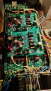
On the first picture I posted you can actually see the washer on a slight slant where I foud it (zoom in alot), not making contact.
That picture was taken when all tested good and I was ready to put in the last row of transistors. Put them in and flipped the amp back around,
the washer fell flat and made the short.

A couple of questions going forward:

Can I go all in on the transistors on L right away or should I go one row at a time? (still all in on R side)

The bring up instructions says to temporarily place a 10Kohm resistor between each channel output and dc ground.
I placed these on the dc protect board on the output connections (J 1.1 to J 1.3 and J 2.1 to J 2.3). (no relay mounted on dcp) is that ok?
The instructions does not tell me when to remove them, I took them off before installing last row of transistors, what's right?

Then the LED light board, two gray leads from transformer to GRY 4 and 5, polarity not important right?
RED1 from right-ch red speaker terminal on dcp board, WHT2 from white left-ch speaker terminal on DCP board,
BUT BLK3, does that go to dc-ground bus bar or DC-ground on DCP board or GND_OUT1 on left channel backplane?

Thank's alot for the help so far, this forum is awesome, I have learned so much after many many hours of reading in here.


Paul.
 

Hexis22

Chief Journeyman
Joined
Dec 28, 2022
Messages
677
Location
Wisconsin
#8
Can I go all in on the transistors on L right away or should I go one row at a time? (still all in on R side)

The bring up instructions says to temporarily place a 10Kohm resistor between each channel output and dc ground.
I placed these on the dc protect board on the output connections (J 1.1 to J 1.3 and J 2.1 to J 2.3). (no relay mounted on dcp) is that ok?
The instructions does not tell me when to remove them, I took them off before installing last row of transistors, what's right?

Then the LED light board, two gray leads from transformer to GRY 4 and 5, polarity not important right?
RED1 from right-ch red speaker terminal on dcp board, WHT2 from white left-ch speaker terminal on DCP board,
BUT BLK3, does that go to dc-ground bus bar or DC-ground on DCP board or GND_OUT1 on left channel backplane?

Thank's alot for the help so far, this forum is awesome, I have learned so much after many many hours of reading in here.
Good to see you're making progress.

Outputs
Given the issues to date, I recommend you insert the outputs one row at a time and confirm functionality after each row. Take your time and be thorough, enjoy the process...

LED light board
- Two Grey wires are AC and polarity is not important
- Place a ring terminal under the DCP Right channel output screw (output side of relay) and run a Red wire to the light board
- Place a ring terminal under the DCP Left channel output screw (output side of relay) and run a White wire to the light board
- Run a Black wire from the DC ground buss bar to the light board
 

Paul Haaskjold

New Around These Parts
Joined
Dec 16, 2022
Messages
9
#9
Good to see you're making progress.

Outputs
Given the issues to date, I recommend you insert the outputs one row at a time and confirm functionality after each row. Take your time and be thorough, enjoy the process...

LED light board
- Two Grey wires are AC and polarity is not important
- Place a ring terminal under the DCP Right channel output screw (output side of relay) and run a Red wire to the light board
- Place a ring terminal under the DCP Left channel output screw (output side of relay) and run a White wire to the light board
- Run a Black wire from the DC ground buss bar to the light board
Thank's,
Will do, slow and steady it is:)
 

mlucitt

Veteran and General Yakker
Joined
Jun 24, 2011
Messages
3,469
Location
Jacksonville, FL
#12
Good to see you're making progress.
Thanks for the assist. You took the troubleshooting words right out of my mouth. Spot on.

The Bring Up Instructions are very generic and meant to apply to a wide variety of upgrade scenarios. The 10K resistors give a path for current flow from the outputs to the Chassis; current will take the path of least resistance. So if you measure less than 10K on the Left and Right output channels, you have a short or partial short. There should be a step to remove the 10K resistors after this test.

All your Grounds should be tied to the Buss Bar between the Bulk Power Supply Capacitors, this is the "Single Terminal AC/DC Return" (STAR) Ground. I just made that up but it is more accurate than a representation of a 'star'.

This was the common practice in the recording studios to prevent Ground Loops, in which every equipment chassis and the racks themselves (and there may be almost a hundred devices) were mechanically connected by wires to a single point. This single point was then connected to the AC Circuit Breaker Panel Ground or a large copper rod driven 6-10 feet into the ground. This way every piece of gear still has AC fault protection, and no Earth Grounds are tied together.
 
Last edited:

Paul Haaskjold

New Around These Parts
Joined
Dec 16, 2022
Messages
9
#15
Thank god it's Friday:)

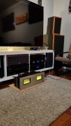
I have been playing now for a week, and here is my two cents:

*Channel separation and sound stage is much improved, Joe's components are top quality and will last a lifetime or two.
*Transformer buzzes a little, normal I think. (not audible through speakers) Is there a transformer upgrade avalible? Is it needed?
*Before the rebuild there was a slight tweeter hiss (white noise), this is still there. Depending on input source the "hiss" is less or more.
I tried to connect this through a lot of coiled up cheap signal wire and the "hiss" was loud! On my Abrahamsen pre amp setup (all balanced exept last step to PL) it was barely noticable. It seems ticklish on the inputs. (recommendations on good signal cables?)
*My VU meters are not alike, one is Jewell and the other is Dixon. My father who bought this amp new swears none have been swapped,
could this be? and is it possible to get a new one so they match? (they are quite different, unbelievable I have not noticed before now)
*This project was a lot of fun, and I learned a lot. i didn't know how to solder before, now I think I got it to a decent level.

Wish all you guys a happy weekend, cheer's!

Paul
 

Attachments

Top