Testing complete

Replaced F2 fuse.
C11, Q51, D52L, VR51L, Q6L ond Q9L all tested out equal to right channel.
Your chart was exellent Mark

One row of transistors mounted on L all in on R, variac and DBT.
Measurements made:
72vdc +/- on caps and backboards.
0vdc on both outputs

15vdc +/- on driverboard.
Bias back to 0.350 on both channels.
Seems like I have risen from the abyss in one piece. *sigh of relief*
Am I good to go forward?
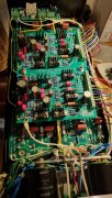
On the first picture I posted you can actually see the washer on a slight slant where I foud it (zoom in alot), not making contact.
That picture was taken when all tested good and I was ready to put in the last row of transistors. Put them in and flipped the amp back around,
the washer fell flat and made the short.
A couple of questions going forward:
Can I go all in on the transistors on L right away or should I go one row at a time? (still all in on R side)
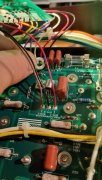
The bring up instructions says to temporarily place a 10Kohm resistor between each channel output and dc ground.
I placed these on the dc protect board on the output connections (J 1.1 to J 1.3 and J 2.1 to J 2.3). (no relay mounted on dcp) is that ok?
The instructions does not tell me when to remove them, I took them off before installing last row of transistors, what's right?
Then the LED light board, two gray leads from transformer to GRY 4 and 5, polarity not important right?
RED1 from right-ch red speaker terminal on dcp board, WHT2 from white left-ch speaker terminal on DCP board,
BUT BLK3, does that go to dc-ground bus bar or DC-ground on DCP board or GND_OUT1 on left channel backplane?
Thank's alot for the help so far, this forum is awesome, I have learned so much after many many hours of reading in here.
Paul.


