
You are using an out of date browser. It may not display this or other websites correctly.
You should upgrade or use an alternative browser.
You should upgrade or use an alternative browser.
Need help verifying if the PL14_20 Control board kit will work in my 400S2
- Thread starter dmccan13
- Start date
dmccan13
Journeyman
- Joined
- Jan 6, 2022
- Messages
- 60
Ok, so from the pin to the respective output terminal. Can do. Thank you!They will go to a ring lug placed underneath the 4-40 nut on the output terminal posts.
dmccan13
Journeyman
- Joined
- Jan 6, 2022
- Messages
- 60
I forgot to ask about that! I saw it on Don's website, but wanted to ask what to remove. Thank you George!He also needs to remove the Zoebel Network from the DCP. That big ass resistor and associated cap. Working today, no time to find a photo. Maybe later.
dmccan13
Journeyman
- Joined
- Jan 6, 2022
- Messages
- 60
Looks like C8 and C9 from other people's picsI forgot to ask about that! I saw it on Don's website, but wanted to ask what to remove. Thank you George!
Or just clip off the big resistors and leave it as that as those caps are in series.
I like to remove all the unused components and solder the through holes shut, that's just me.
OCD is our middle name...
")
dmccan13
Journeyman
- Joined
- Jan 6, 2022
- Messages
- 60
Ha! Setting a new standardOr just clip off the big resistors and leave it as that as those caps are in series.
I like to remove all the unused components and solder the through holes shut, that's just me.
Thank you for the help and the pic. I relied heavily on your pics for the Rg316. In fact, they're still open in a different tab. Couldn't have done it without those.ABebar
Journeyman
I literally JUST asked on another thread if this was applicable to PL400 as well as the 700. Consider my question answered2 other things, well maybe 3.
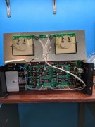
- Get those 2 AC wires going to the thermal cutout paired right next to each other for the entire run to cancel the AC field they generate.
- Get the copper plate joining the 2 RCA inputs in place It is ESSENTIAL that you have the copper plate installed and connecting the 2 RCA input jacks. This shunts any external ground loops associated with cable connections from entering the amp’s separate signal paths and creating various degrees of ground looping. In other words, it makes the amp INTERNALLY immune to cabling effects from outside the amp. This does not say that you cannot still have external ground looping, it does say that this keeps the amp internals out of the equation. No build I have ever done has removed this copper plate. Remember, the RCA jacks and this copper plate MUST be isolated from the chassis.
- Disconnect and remove the two ground wires running from the backplane pin 5L and 5R which run to the control board pin 5L and 5R Phoenix connector.
Along the bottom, run two new, separate 22AWG wires from a single solder lug on the single point ground copper bus bar to pin 5L and 5R on the control board. The solder lug goes underneath the 10-32 (or M5 if you have our newer caps) screw on the bottom B- bulk cap positive terminal which attaches to the copper bus bar. The wire to 5L is approximately 5” long and the wire to 5R is approximately 10” long, your measurements may be adjusted to suit how you lace these in. You should be able to use one of the #10 solder lugs provided in the White Oak Audio wire kits to accomplish this.
2 other things, well maybe 3.
- Get those 2 AC wires going to the thermal cutout paired right next to each other for the entire run to cancel the AC field they generate.
- Get the copper plate joining the 2 RCA inputs in place It is ESSENTIAL that you have the copper plate installed and connecting the 2 RCA input jacks. This shunts any external ground loops associated with cable connections from entering the amp’s separate signal paths and creating various degrees of ground looping. In other words, it makes the amp INTERNALLY immune to cabling effects from outside the amp. This does not say that you cannot still have external ground looping, it does say that this keeps the amp internals out of the equation. No build I have ever done has removed this copper plate. Remember, the RCA jacks and this copper plate MUST be isolated from the chassis.
- Disconnect and remove the two ground wires running from the backplane pin 5L and 5R which run to the control board pin 5L and 5R Phoenix connector.
Along the bottom, run two new, separate 22AWG wires from a single solder lug on the single point ground copper bus bar to pin 5L and 5R on the control board. The solder lug goes underneath the 10-32 (or M5 if you have our newer caps) screw on the bottom B- bulk cap positive terminal which attaches to the copper bus bar. The wire to 5L is approximately 5” long and the wire to 5R is approximately 10” long, your measurements may be adjusted to suit how you lace these in. You should be able to use one of the #10 solder lugs provided in the White Oak Audio wire kits to accomplish this.
Regarding 3. ... what is up with that? Meaning, why disconnect the AGND link from the backplane to the control board and instead use the star point/bus bar ground? Is this particular to the Series II or should other builds (PL400, PL700, etc) also do this?
- Joined
- Jan 14, 2011
- Messages
- 75,905
- Location
- Gillette, Wyo.
- Tagline
- Halfbiass...Electron Herder and Backass Woof
To prevent ground loops..