WOPL Sniffer
Veteran and General Yakker
I'd take the aluminum bell off that holds the bulk caps and see if the insides look like the outside. If it was submerged, and the inside shows it, throw it in the scrap pile.
This is the hard advice I came here for. Second time I've been told to leave my comfort zone. I'll move to contact on that. Thank you!I'd take the aluminum bell off that holds the bulk caps and see if the insides look like the outside. If it was submerged, and the inside shows it, throw it in the scrap pile.
Hard to see but the front looks clean. Can I get away with using this for now?
At some point I'd like to do the full backplane kit and judging from other parts I've seen transformers ain't cheap. So if it'll be fine until then, I can keep an eye out and budget for it. That's my logic, flawed though it may beIt's a BIG job to change out a transformer so IF you are going to use it, make sure it's good to go.
I do have a DBT, with 60, 75, and 100 ready to go. Since the rail fuses are out it doesn't matter that I have all the outputs and cooling fins removed correct? Guess my question is, how "assembled" does it need to be? I haven't replaced the fins and the outputs because I want to take the fins to a friend of mine tomorrow and see what he says about the staining. Was also searching for some RCA410s to replace the driver RCA 66546s (all tested good). Saw some other threads saying not to trust transistors that old when doing a WOPL.
I do have a DBT, with 60, 75, and 100 ready to go. Since the rail fuses are out it doesn't matter that I have all the outputs and cooling fins removed correct? Guess my question is, how "assembled" does it need to be? I haven't replaced the fins and the outputs because I want to take the fins to a friend of mine tomorrow and see what he says about the staining. Was also searching for some RCA410s to replace the driver RCA 66546s (all tested good). Saw some other threads saying not to trust transistors that old when doing a WOPL.
Which stuff? I want to get this right.If yer gonna do a WOPL, that stuff is unusable
Thank you! For both. I'm not sure what it is. Some look like drips running down part way, some are large splotches. I've tried windex, IPA, magic eraser, barkeepers friend. It looks like surface staining, not etched in. I'll post pics tomorrow. Need to be up at 0400Yes you can leave rail fuses out, and check power supply voltages without outputs in.
66546's are rebadged RCA 410's...
Staining of what??


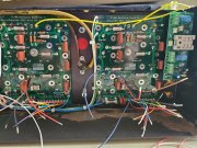
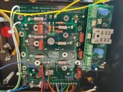
They will go to a ring lug placed underneath the 4-40 nut on the output terminal posts. DCP output Red and White output posts will add a #4 ring lug terminal under each of the 4-40 nuts. The red and white 22AWG wires will attach to these ring terminals with the other end going to the respective input terminals on the Light Board. This will keep the meters from dancing on power up and power down. If you have the DCP, you might as well take advantage of its capabilities.So, since we last talked, the transformer has been checked, the PL14_20 has been assembled, the backplane boards are in and mostly wired and the Cylon boards have been rebuilt. But I'm sort of stuck wiring in Don's DCP and hoping somebody can give me a nudge in the right direction. Out 2 L and R from the backplanes go to J1-1 and J2-1, J1/2-3 will go to star ground as well as J3-2, J3-3 to the Tformer as I understand it. I can use Fused B+ out on the right backplane for the DC input on the DCP correct?
Also, in the backplane wire connections chart, it says Out 1 on both boards would normally go to the Cylon meters, but if using the DCP, the Cylon wires will come from the DCP outputs. So I desoldered Out 1 on both boards and pulled the wires (concerned about that decision). So I'm confused about which connectors on the DCP should go to Pin 1 and 6 on the Cylon meters. In other pictures I found, it looks like Out 1 still goes to the Cylons even though they have the DCP installed. Also, I followed George's lead and replaced the beldin wires from the pots with Rg316 which I will run to R1/2and L1/2, and I pulled the copper ground from the RCA's and went back to the grounding tabs that came with them.
As always, I appreciate any help! You guys go me this far and I'm super grateful.View attachment 63651View attachment 63652View attachment 63653
2 other things, well maybe 3.So, since we last talked, the transformer has been checked, the PL14_20 has been assembled, the backplane boards are in and mostly wired and the Cylon boards have been rebuilt. But I'm sort of stuck wiring in Don's DCP and hoping somebody can give me a nudge in the right direction. Out 2 L and R from the backplanes go to J1-1 and J2-1, J1/2-3 will go to star ground as well as J3-2, J3-3 to the Tformer as I understand it. I can use Fused B+ out on the right backplane for the DC input on the DCP correct?
Also, in the backplane wire connections chart, it says Out 1 on both boards would normally go to the Cylon meters, but if using the DCP, the Cylon wires will come from the DCP outputs. So I desoldered Out 1 on both boards and pulled the wires (concerned about that decision). So I'm confused about which connectors on the DCP should go to Pin 1 and 6 on the Cylon meters. In other pictures I found, it looks like Out 1 still goes to the Cylons even though they have the DCP installed. Also, I followed George's lead and replaced the beldin wires from the pots with Rg316 which I will run to R1/2and L1/2, and I pulled the copper ground from the RCA's and went back to the grounding tabs that came with them.
As always, I appreciate any help! You guys go me this far and I'm super grateful.View attachment 63651View attachment 63652View attachment 63653
Roger that Joe, WILCO on all above. I didn't realize how important the copper plate was, I'll get it cleaned up and reinstalled. Glad I posted this before carrying on. THANK YOU!2 other things, well maybe 3.
- Get those 2 AC wires going to the thermal cutout paired right next to each other for the entire run to cancel the AC field they generate.
- Get the copper plate joining the 2 RCA inputs in place It is ESSENTIAL that you have the copper plate installed and connecting the 2 RCA input jacks. This shunts any external ground loops associated with cable connections from entering the amp’s separate signal paths and creating various degrees of ground looping. In other words, it makes the amp INTERNALLY immune to cabling effects from outside the amp. This does not say that you cannot still have external ground looping, it does say that this keeps the amp internals out of the equation. No build I have ever done has removed this copper plate. Remember, the RCA jacks and this copper plate MUST be isolated from the chassis.
- Disconnect and remove the two ground wires running from the backplane pin 5L and 5R which run to the control board pin 5L and 5R Phoenix connector.
Along the bottom, run two new, separate 22AWG wires from a single solder lug on the single point ground copper bus bar to pin 5L and 5R on the control board. The solder lug goes underneath the 10-32 (or M5 if you have our newer caps) screw on the bottom B- bulk cap positive terminal which attaches to the copper bus bar. The wire to 5L is approximately 5” long and the wire to 5R is approximately 10” long, your measurements may be adjusted to suit how you lace these in. You should be able to use one of the #10 solder lugs provided in the White Oak Audio wire kits to accomplish this.
