
You are using an out of date browser. It may not display this or other websites correctly.
You should upgrade or use an alternative browser.
You should upgrade or use an alternative browser.
My PL400 Series 1 Rebuild
- Thread starter jle
- Start date

Yes, BUT ONLY AT THAT RCA JACK INPUT POINT. It shunts any possible external ground loops by virtue of that.So, 2L and 2R thereby get tied together, correct?
jle
New Around These Parts
I am getting close to the wiring for the WOPL-400 being ready for the 1st set of "Bring Up" tests for the first row of transistors.
QUESTION: I have been wiring in the Watts Abundant DC Protection ("DCP") board along with the backplane boards. Can the testing be done with the DCP in place?
QUESTION: I have been wiring in the Watts Abundant DC Protection ("DCP") board along with the backplane boards. Can the testing be done with the DCP in place?
Yes. As you bring up the line voltage with the Variac, the click of the DCP relay is a indication that all is well.
I can't remember the exact VAC that the DCP relay energizes at, maybe 80 VAC.
If you bring line voltage up to 115-120, and no click, that's a indication of a problem.
The DCP relay click is a good indication, along with the DBT and test meters, that all is going as planned.
No click, you've got a problem.
Hi Jon
You should probably post a collage of your build photos here so that the eagle eyes on this forum can point out anything that needs fixing before powering up.
You should probably post a collage of your build photos here so that the eagle eyes on this forum can point out anything that needs fixing before powering up.
jle
New Around These Parts
Hi Jon
You should probably post a collage of your build photos here so that the eagle eyes on this forum can point out anything that needs fixing before powering up.
Will do!
jle
New Around These Parts
Okay, I have spent several hours trying to figure this out and/or find mention in the documentation or in this forum. I think I am getting tripped up by the various generations of PL400s that are providing text descriptions and photos, trying to get everything aligned for my config. Since I have struck out, I'm now asking for some help...
I am trying wire up the new PS caps. The + and - obviously connect to the bridge snubber. But where else? Photos show two wires off of each connector, presumably to fuses? But the wire count on fuse photos doesn't match.
HELP! Where do the PS caps get wired to?!
I am trying wire up the new PS caps. The + and - obviously connect to the bridge snubber. But where else? Photos show two wires off of each connector, presumably to fuses? But the wire count on fuse photos doesn't match.
HELP! Where do the PS caps get wired to?!
Last edited:
Did you look carefully at slide 89 to 97 of the slide show that I sent you?Okay, I have spent several hours trying to figure this out and/or find mention in the documentation or in this forum. I think I am getting tripped up by the various generations of PL400s that are providing text descriptions and photos, trying to get everything aligned for my config. Since I have struck out, I'm now asking for some help...
I am trying wire up the new PS caps. The + and - obviously connect to the bridge snubber. But where else? Photos show two wires off of each connector, presumably to fuses? But the wire count on fuse photos doesn't match.
HELP! Where do the PS caps get wired to?!
jle
New Around These Parts
Did you look carefully at slide 89 to 97 of the slide show that I sent you?
Yes, I did. That is the basis for my confusion. The photos (especially #95 and #96) show:
- two fat green wires (presumably 16 AWG) going to B+ fuse tip
- two fat green wires going to B+ fuse shell
- two fat blue wires going to B- fuse tip
- two fat blue wires going to B- fuse shell
- one fat green wire attached to PS cap + and appears to be heading to B+ fuse (but uncertain tip or shell)
- one fat blue wire attached to the PS cap - and appears toa be heading to B- fuse (but uncertain tip or shell)
- two 22 gauge green wires to B+ fuse tip (one left, one right)
- two 22 gauge blue wires to B- fuse tip (one left, one right)
- two 16 gauge green wires to B+ fuse shell (one left, one right)
- two 16 gauge blue wires to B- fuse shell (one left, one right)

jle
New Around These Parts
Are you talking about the green and blue wires from the rectifier?
These supply DC to the supply caps.
The wiring to the fuse holders is straightforward.
The white wiring is grounds.
I have identified the wires from the rectifiers to the caps. The wiring to the fuse holders is NOT straightforward (to me anyway). Here's what seems inconsistent to me. Let's just focus on the green wires:
- There are 2 green wires from the backplane boards to the B+ fuse tip (per the instructions for the backplane wiring).
- There are 2 green wires from the backplane boards to the B+ fuse sleeve (per the instructions for the backplane wiring).
- So far, so good -- this is consistent with the appearance of the fuse holders on slide #95 (except for the gauges of the wires). A total of 4 wires going to the B+ fuse holder.
- There are 2 green wires attached to the + terminal of the PS cap (on the right side of the photo). One comes from the rectifier.
- Where does the other green wire on the + terminal go?? It looks like it is heading to the fuse holders. In which the B+ fuse holder should have five green wires (4 from the backplane boards and 1 from the PS cap + terminal).
- It is possible that there are 3 green wires to the B+ fuse holder tip, just not shown well. But the B- fuse holder tip clearly only has 2 wires.
My guess is that I need a wire from the + terminal of the PS caps to the B+ fuse holder tip. And a wire from the - terminal of the PS caps to the B- fuse holder tip. But I don't want to build based on guesses.
-Jon
I see your point.
There are 3 green (B+) coming off the TIP of the B+ fuse holder.
There are 2 green (B-) coming off the TIP of the B- fuse holder.
Where does that 3rd green wire go? Why are they different?
To the unfused B+ bottom LHS on the left back plane board. Then a additional wire for the other back plane board
Remember, fuse holder tips are wired hot unfused, the shell is wired fused.
The fuse holder tips on the amp in the attached photo is wired without a jumper between the boards.
Each has 3 wires, one to the supply cap, and one to the B+ or B- UNFUSED solder pad on each backplane board.
Hope this helps.
Pay attention to getting the fuse connections correct and run individual wires(preferable) or a jumper.
The photo shows old revision boards, yours are newer. Joe's probably made a revision to use a jumper to reduce the wire load.
You'll see it once you understand.
Attachments
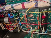
Lets focus on the green wires to the fuseholder which is the B+ supply (the blue fuseholder is identically wired for the B-).Yes, I did. That is the basis for my confusion. The photos (especially #95 and #96) show:
The wiring instructions for the backplane boards call for:
- two fat green wires (presumably 16 AWG) going to B+ fuse tip
- two fat green wires going to B+ fuse shell
- two fat blue wires going to B- fuse tip
- two fat blue wires going to B- fuse shell
- one fat green wire attached to PS cap + and appears to be heading to B+ fuse (but uncertain tip or shell)
- one fat blue wire attached to the PS cap - and appears toa be heading to B- fuse (but uncertain tip or shell)
So, the wire count called for does not match the wire count in the photo. (NOTE: The attached photo is slide #95 from your slide show, NOT my build!). Where do the wires from the PS cap + and - go? I am guessing that slide 95 is from a slightly earlier version than my backplane instructions.
- two 22 gauge green wires to B+ fuse tip (one left, one right)
- two 22 gauge blue wires to B- fuse tip (one left, one right)
- two 16 gauge green wires to B+ fuse shell (one left, one right)
- two 16 gauge blue wires to B- fuse shell (one left, one right)
View attachment 84060
One fat green wire and 2 smaller wires go to the fuseholder tip. The fat one is the B+ from the bulk cap. The smaller ones are the feeder wires to the unfused B+ that go to the left and right backplanes.
2 fat green wires exit from the fuseholder shell, one to the left backplane and one to the right terminating into the B+ Fused connection points.
The wire list matches this description.
Rinse and repeat for the blue side.
jle
New Around These Parts
Okay. Got the backplane boards wired to the fuse holders and added the B+ and B- connections from PS caps to fuse holders. Phew!
Next question: I have a 1K ohm 5W resistor to discharge the PS caps (between testing each row of output transistors). To accomplish the discharge, do I just connect the resistor between the + and - terminals of the cap? Is it worth it to measure the voltage (in parallel) while things are discharging? Do I discharge the caps one at a time or as a pair?
Next question: I have a 1K ohm 5W resistor to discharge the PS caps (between testing each row of output transistors). To accomplish the discharge, do I just connect the resistor between the + and - terminals of the cap? Is it worth it to measure the voltage (in parallel) while things are discharging? Do I discharge the caps one at a time or as a pair?
Last edited:
jle
New Around These Parts
Answering my own question, I found the cap-discharging scene in the Bob-a-licious videos. B+ and B- each get connected through a resistor to the bus bar. This seems to me that this is electrically the same as connecting B+ directly to B-, as the "ground" in a PL-400 is really a common (it doesn't run to "earth" as our British friends would say). I am still searching for the proper soundtrack to use to prevent flesh burns (Bob seems to feel that this can be helpful).
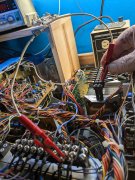
I made a nice cap discharging jumper before building my first WOPL.
Once you get the outputs in, the caps will self discharge.
I still use it for other equipment, comes in very handy to prevent accidents.
This tape deck carries a lot of capacitance when shut off.
I discharge the caps before taking anything apart, prevents shorts and stressed components.
Once you get the outputs in, the caps will self discharge.
I still use it for other equipment, comes in very handy to prevent accidents.
This tape deck carries a lot of capacitance when shut off.
I discharge the caps before taking anything apart, prevents shorts and stressed components.
Attachments
jle
New Around These Parts
Thanks for that insight.Yes. As you bring up the line voltage with the Variac, the click of the DCP relay is a indication that all is well.
I can't remember the exact VAC that the DCP relay energizes at, maybe 80 VAC.
If you bring line voltage up to 115-120, and no click, that's a indication of a problem.
The DCP relay click is a good indication, along with the DBT and test meters, that all is going as planned.
No click, you've got a problem.
With the DCP board in place and its relay installed, there is zero resistance between the speaker binding posts on each channel. When I remove the relay, that short goes away. Is that what I should expect? I am guessing that the relay is normally closed, shorting the + and - for each speaker as protection. When the Variac hits the magic mark, I should hear the relay click, which I am guessing means it has opened and the voltage across the binding posts can now be measured (it should be 0).
Have I got that correct?
My understanding that the "click" is the relay opening and ungrounding the amps output.
I've never put a ohm meter across the circuit to check this, however.
The guys who repair these would know for sure.
My three units have been trouble free so I've never investigated.
I did have one relay that was "slow" at first and needed "exercising". Wasn't wiring or DC, was the relay itself,
I've never put a ohm meter across the circuit to check this, however.
The guys who repair these would know for sure.
My three units have been trouble free so I've never investigated.
I did have one relay that was "slow" at first and needed "exercising". Wasn't wiring or DC, was the relay itself,
The Watts Abundant board uses a DPDT relay on the PL400 version. When the amp is powered off or the relay is de-energized due to a fault or during the power up delay, the speaker is grounded. Once energized, the relay armature moves to connect the speaker to the amp output. The speaker is connected to the armature common. The NC pole is connected to ground and represents the de-energized resting position. The NO pole is connected to the amp output and represents the energized position.