My New Early Model PL400 w/ 4 Fin Heat Sink

VSAT88

Veteran and General Yakker
Joined
Sep 7, 2017
Messages
1,866
Location
Phenix City Alabama
Tagline
Like my BlueTooth ?
#41
BTW. I do not know if I posted images of the bias transistor fix that Lee helped me with. I would not doubt that that fix, the way he showed me to do it and the way it was done will outlast the amplifier. It is a much better way. If you need me to I can post the images.
 
Last edited:

punchback

Journeyman
Joined
Jan 8, 2019
Messages
124
#42
Oh yeah! 15,000uF 100V caps and a 50A 600V bridge. I can't wait to to put them in. I've also requested an invoice for a output relay kit from Watts Abundant. A little while ago I was working on the BOM, at Mouser, for the relay board. I think you forgot a couple of caps that should be re-use from the zoeble network. Could they just be ordered from Mouser? If so does anyone have a suggested p/n?
 

punchback

Journeyman
Joined
Jan 8, 2019
Messages
124
#45
I looked and the caps on the zoeble network are . 1 100V . They looked like film caps. Looks like lots of choices like Wima. Probably just order them with the relay board BOM.
 

laatsch55

Administrator,
Staff member
Joined
Jan 14, 2011
Messages
74,943
Location
Gillette, Wyo.
Tagline
Halfbiass...Electron Herder and Backass Woof
#48
Gonna have to drill a hole in the back. White Oak boards have 2 holes, in the middle, like the PL14, Pl020 boards...
 

Bradrock

Veteran and General Yakker
Joined
Jun 7, 2017
Messages
1,563
Location
Alton Mo.
Tagline
---I run with Scissors
#50
Member Mark Comer has done a bunch of videos on his WOPL adventures. That's how I found this place. His control board vid will give you a look at what all is in the kit.


VSAT88

Veteran and General Yakker
Joined
Sep 7, 2017
Messages
1,866
Location
Phenix City Alabama
Tagline
Like my BlueTooth ?
#51
Yep, I did forget to put those in on the start (the caps on Dons board) but before it was done they were caught and put in . I used one off the zobel and two I had here. Lee told you about the caps around the BR in the posts before right ? I hope you got a big ole hot iron to put that and the protect board in.
 

punchback

Journeyman
Joined
Jan 8, 2019
Messages
124
#52
I've watched a few of Mark's videos. They're both informative and entertaining. I have a pretty decent Weller soldering station so I should be good for assembly. I also have the caps for the bridge mod in the order.
 

punchback

Journeyman
Joined
Jan 8, 2019
Messages
124
#54
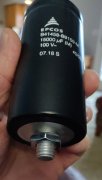
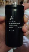
I got my parts in but had a little oversight. The 15000 uF 100V caps turned out to be stud mount. I've never seen them before... I hate to return them as it'll cost $12 dollars or so to ship them. I was thinking of drilling some holes and using the stud. It will fit right in with the all of the other half dozen screws on that side of the case. I also thought about cutting the stud off. Anyone else have any experience with this kind of cap? Would cutting the stud off or shortening it cause a problem? Not including the stud they're almost exactly the same size as the existing caps.

DSC_0238~01.jpg DSC_0237~01.jpg
 

VSAT88

Veteran and General Yakker
Joined
Sep 7, 2017
Messages
1,866
Location
Phenix City Alabama
Tagline
Like my BlueTooth ?
#56
If you don't care about keeping everything original drill a hole and bolt them in !
Edited !
 
Last edited:

jbeckva

Admin/Server Dude MAA Guy
Staff member
Joined
Jun 11, 2010
Messages
6,850
Location
Powhatan, Virginia, United States
Tagline
WassupYa Mang?
#57
Check the resistance stud to negative terminal, and if you have a short there then think about what that would mean if both were electrically bonded when bolting them to the chassis. :scratch:
 

punchback

Journeyman
Joined
Jan 8, 2019
Messages
124
#58
The new caps are connected negative terminal to the stud. The existing setup is negative to the chasis. So they are the same in that respect. I'm not sure if it's going to be a problem for me in respect to keeping it original... I'll have to sleep on it.
 

punchback

Journeyman
Joined
Jan 8, 2019
Messages
124
#59
After looking at the schematic I guess bolting them to the chassis wouldn't be such a good idea. It might be OK for the +75 rail but the -75 rail would be connected to the chassis. That doesn't seem like a good idea. I guess I have to send them back :confused:.

Since I'm going to be placing another Mouser order I figured I'd get replacements for the few electrolytics that are on the, I guess, PL400C board. Based on the actual board each channel has (1) 10 uF/50V, (2) 40uF/15V, and (1) 100uF/10V. I already have a replacement for the 100uF/10V as specified by laatsch55 (470uF/50V).

On the other three I really cannot find them on the schematic from HiFiEngine. Should I just go with what's there keeping the uF that same and upping the voltage if I have to??

Alan
 

laatsch55

Administrator,
Staff member
Joined
Jan 14, 2011
Messages
74,943
Location
Gillette, Wyo.
Tagline
Halfbiass...Electron Herder and Backass Woof
#60
Yep, always go with what's on the board in.lieu of a documented revision or a walking talking revision like Ed Blackwood.
 
Top